Eng-Tips is the largest engineering community on the Internet

Intelligent Work Forums for Engineering Professionals

AWWA D100-21 Wind Force Coefficient, Cf

Status
Not open for further replies.

Grittz

Structural
May 11, 2022
4
0
0
US
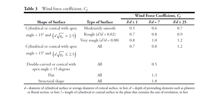
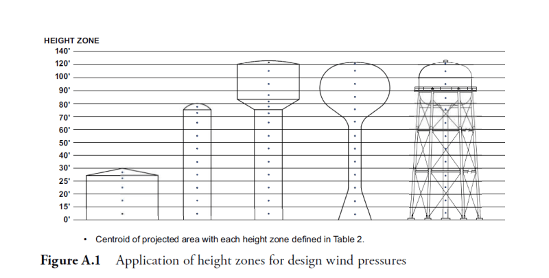
I am working on a structural analysis for a water tower and am looking for clarification on calculating the wind force coefficient Cf. Table 3 provides values to use based on the L/d ratio, and defines L as the length of cylindrical or conical surface in the plane that contains the axis of revolution. In the commentary, there's a provided figure that depicts the height zones and where you should take cuts to apply the appropriate Kz. Should the L value be the height of the centroid with respect to the ground, the overall height of the structure, or the distance between the two different elevations for the respective cut?

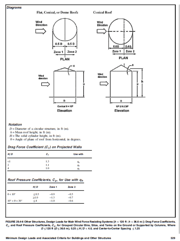
The confusion is coming from some of the figures in chapter 29 of ASCE 7-16, which is what AWWA D100-21 is based upon. In ASCE the Cf (and the roof pressure coefficient, Cp, are based on the on the solid cylinder height.

Screenshot_2024-05-14_114154_otce7m.png

Screenshot_2024-05-14_114323_d2hyul.png

Screenshot_2024-05-14_122300_gyoyrj.png


Thanks in advance for the help!
 
Replies continue below

Recommended for you

I understand L to be the length of the cylinder, unrelated to its location. For a pedestal or shell, I would take it as length of that element. For a leg tank, the total length of the leg.

On the zones-
You calculate the wind pressure, but then it must be at least 30Cf. In non-coastal areas, you won't hit 30CF until way high. So the majority of tanks, you can omit that whole zone mess and just use the 30Cf. But always check how high that 30Cf is exceeded, and everything below there is simplified.
Also note the square root of qz distinction, which will govern for sway rods, handrails, and the like.

Note that the wind loading has been updated, so that tanks built under older versions may have higher or lower loading under the newer version.

I note that you show the "Grouped" tank data from ASCE, not the "isolated" data, which is what most municipal water towers would fall under.
 
Totally agree on the zones and the 30Cf controlling for most situations. My question is really about what to use for the L value because that seems to be the factor that will matter at the end of the day. For instance when considering a pedestal tank (fourth tower from the left in figure A.1 to make sure we're referring to the same thing), would you consider the shaft as a whole an 'element', or would you break it up where the steel thickness changes, or where the height zones are defined? Seems like you'd end up with a greater wind pressure when considering L to be the entire shaft length vs breaking it up into the smaller elements.
 
I would consider the shaft as a whole for that L length. The variation in Cf for that one item should be a fairly small part of the overall wind load, though.
 
Status
Not open for further replies.
Back
Top