Continue to Site

Eng-Tips is the largest engineering community on the Internet

Intelligent Work Forums for Engineering Professionals

  • Congratulations IDS on being selected by the Eng-Tips community for having the most helpful posts in the forums last week. Way to Go!

Axial flow jet pump cone geometry

Status
Not open for further replies.

rotarypower

Mechanical
Oct 4, 2003
10
Hi guys wondering if anyone knows where I can get information about the geometry of a jet pump cone for a clear water application?

I need to design a cone for a vein mounted cone off from a axial jet pump.

Can someone lead me in the right direction what profiles I can use, and basic hydrodynamic theory that will be used in such a scenario?

My instincts tells me the cone profile should match the drag profile of the center section of the vein housing, but is there any information someone can supply about theory of such a circumstance, and optimization?

A question that has also been posed, is that turbulators are not needed in a profile of this sort correct? With a cone profile (if designed correctly) there is no draft effect that should happen correct?

BTW there is a wealth of pump info here if you have not seen it yet.
Thanks to the author!

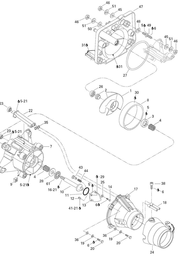
pic of pump diagram. If it does not load properly, please inform me and I will link to a site that will allow it.

 
Replies continue below

Recommended for you

are you asking about the design of a discharge diffuser for an axial flow pump?

Naresuan University
Phitsanulok
Thailand
 
Sorry the response was delayed spent a little time in HI :).

Yes I think you could it could be called a “discharge diffuser “

It is part number 13 in the microfiche diagram that I posted.
Does the pic show up alright when clicked? Or does it require logging into the site to view? I tried logging out of the site it was posted and it still loaded for me, and worked today as well.

Just trying to find some info on how to properly design it and the factors that are important if trying to make one from scratch.

Any leads to texts, links or info will be appreciated.

Ah ha! You can post pics manually, just a slightly different format\/


attachment.php
 
Essentially what I am looking for is what 2 dimensional profiles would one choose as a cap cone for the bearing and shaft housing to most efficiently return the water to a laminar nonhollowed out stream?

I have physically measured the existing cone and have derived a mathematical equation that describes the profile of both the housing and the cone, but am really looking for any information that would confirm the theory and correctness of the design, and would like to improve upon it if possible.

The existing cone does not facilitate an ideal circumstance for water flowing over the tip of the cone to join in a naturally laminar flow, as one of the blatantly incorrect features in my mind. I wish to find information pertaining to the ideal circumstances dealing with this scenario, and produce a aluminum replica that is better.

I really have not found any information pertaining to the geometry of such a thing, can any one speculate as to how the geometry would be found based on surrounding factors?


I posted the pic to an outside source incase it does not show up for some.

Thank you for any help or advice you can supply.

jetpump2.jpg
 
The flow has already been straightened thru the difussing section No 7 and I wouldn't think you can improve the shape of the cone No 13 within the current design configuration. Even if you could - what would be the benefit if any - probably unmeasurable.

However, looking at the schematic, you cannot tell if the straightening vanes in section No7 are straight or are actual aerofoil shape - if they are straight as it seems to show in the the schematic, more efficiency could be gained by redesigning the diffusing section to aerofoils to match the discharge angle of the flow leaving the impeller - this would be more advantageous than redesign of the cone No 13.

A few quick thoughts for what they are worth.


Naresuan University
Phitsanulok
Thailand
 
Thank you for taking time to comment :) any input is very much appreciated.

The reason why I wish to know the design parameters is not so much to improve upon the stock part (though this should be easily possible), but I am working on a project that requires knowing what is advantageous and beneficial when creating one from scratch.

Thank you for the tip about the airfoil profile, I was just looking through a older fluids book the other day showing just how much less drag there was compared even to an ellipse. The tear drop shape is defiantly a good profile to use if possible.


I have been looking for info specifically for flow characteristics of a clearwater pump cone, and have not really found any information to speak of on the subject.

I would love some leads to find information pertaining to such a thing.


Does anyone have any opinions as to if I can simply use what information is available for jet engine discharge cones and theory?

I would think the basic principals would hold true for a discharge cone, but water being a much denser material, the recommended length of a cone would probably increase for a given velocity. That and the data found for those is a much greater velocity with no real data in the realm of where I am working.

Similar to the discharge cone on a jet engine \/

components_01.jpg
 
This is what I am planning on for a profile, or something to this effect, if I can find some data supporting transition zones and rate of change for the profile.

I have taken measurements to try and find what others have done, and copy that, but would really like to see some information on what has been found to be the best.

attachment.php
 
Status
Not open for further replies.

Part and Inventory Search

Sponsor