Eng-Tips is the largest engineering community on the Internet

Intelligent Work Forums for Engineering Professionals

  • Congratulations waross on being selected by the Tek-Tips community for having the most helpful posts in the forums last week. Way to Go!

Axial Force distribution to flange weld - Stiffened Extended Shear Plate 1

Status
Not open for further replies.

Ganesh Persaud

Structural
Nov 21, 2018
93
GY
hello everyone,

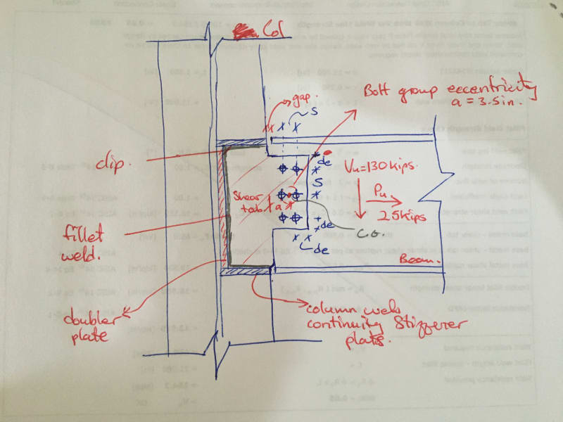
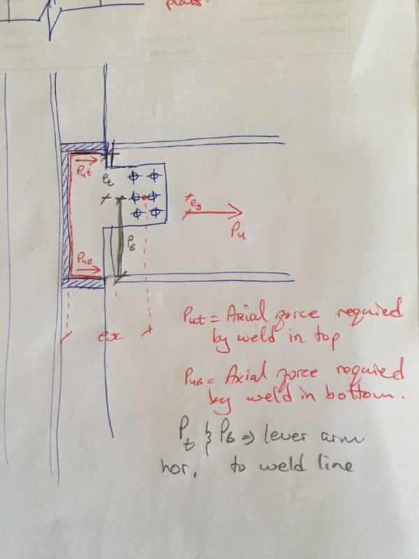
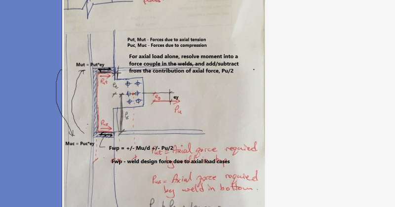
I have a stiffened extended shear plate to a column web connection. The beam is subjected to both shear and axial forces. The beam is also in tension. With respect to axial force, how do I calculate the axial force that would be distributed to the top and bottom flange weld (column continuity stiffener plates)? Since the beam is in tension, I know that there is a larger distribution to the bottom flange but how do I calc it? Any Ref?

Best Regards,
Ganesh Persaud

 
Replies continue below

Recommended for you

DB085573-BEBB-4EFD-B5CA-3F623FD4E957_jfzhdw.jpg


I want to calc the force that the horizontal weld line Would carry. As seen by the continuity plates on the pic.

I know with respect to the c.g of the bolt group to the vertical distance to the top horizontal weld and the bottom horizontal weld would determine the percentage of the full force that would be distributed by the top and bottom weld.
 
I know with respect to the c.g of the bolt group to the vertical distance to the top horizontal weld and the bottom horizontal weld would determine the percentage of the full force that would be distributed by the top and bottom weld.

With respect to the sketch below:

Flange Weld Design -
Mu = Vu*ex ± Pu*ey, ± indicates Pu can either be tension, or compression.
Fw = Mu/d ± Pu/2, d is centroid distance of the horizontal weld.

g_uh2kum.png
 
You have a series of loads acting on your (3) sided weld group - you have direct shear (Vu), direct axial (Pu), as well as rotation caused by Vu*ex and Pu*ey - based on your sketch both appear to induce a clockwise rotation in your weld group.

There should be eccentric weld group tables that cover this situation. Are you AISC? I'm more familiar with CISC, but I'm pretty sure AISC has far more weld design tables and I'm fairly sure one of them covers your condition.

Alternatively, you can do this manually but calculating the line properties of the weld group (use a unit width of 1, and be careful tracking units) - apply all of the loads to your "line section" and you can get your peak demand on the weld group. If you can find the tables that cover this condition you'll probably get a more efficient design.
 
retired13, I understand your sketch as I made ref to AISC 14th Manual, chapter 10, pg 103. figure 10-12.

My question is how do I distribute the Pu into Put and PuB. as seen in the sketch.

95956550_229916891756481_217898220800442368_n_wmcomb.jpg
 
If this is a hypothetical connection, the typical weld analysis methods will provide you with unit force/stress values that vary along each weld leg. You choose the load path, and the force will "flow" toward the stiffest elements. This doesn't seem like a case where the horizontal force should be attributed solely to the continuity plates.

I would avoid this configuration in a "real-life" scenario by using double angles, an end plate, or a pair of flange plates w/ a shear tab. If I had to use an extended plate conx., I would do everything in my power to avoid using a column doubler. There are a number of other things that can be done as well. The odd proportions of the members and connection elements make me think this might be a hypothetical exercise in analyzing weld groups.
 
Hope this helps. Watch out direction of resultant forces - the couple and the axial force can either acting in the same direction (additive), or opposite direction (subtract/negate).

z_g3zqhb.png
 
retired13,
Ganesh Persaud is suggesting that the axial load in the beam is not equally spaced between the top and bottom stiffener plates - thus the bolt group is eccentric to the weld group (pt and pb distances).

So the weld force would be distributed based on NOT Pu/2 as you've shown, but based on those eccentricities.

Ganesh Persaud - this is simply another moment applied to the weld group, additive to the moment from the vertical shear and its eccentricity.

Review the "elastic method" that AISC provides in the 14th manual that you referred to - page 8-12.

Also - the use of applying all the moment and forces to a full weld group (the vertical weld and the two horizontal stiffener welds) assumes that the weld to the doubler plate is as stiff as the stiffener welds, which may be in doubt as the doubler plate is not fully "glued" to the column web but rather welded around its perimeter. It might be prudent to assume vertical shear goes through the doubler plate and all axial and moment resisting forces go through the stiffeners, which is what retired13 was implying with the Pu/2 assumption.


DrZoidberWoop, I can’t neglect the doubler plates because of my moment connection design. For me to remove the double plates, my column section web would be a lot thicker and cost per lb/ft is very expensive. The reason for using the extended shear plate, I already have column continuity plates as required by my moment calcs.

Retired13 as JAE mentioned, he provided a much clearer description of what I was trying to accomplish.

JAE will definitely have a look at the referenced doc and post my findings.

Thanks
 
So he distribute the force Pu into Put and Pub alone the welds? I think the concept is the same, force in the weld +/- couple derived from net moment about the support. This is not a theoretical solution, but suffice for practical applications. Thanks for the note though.
 
OP. I don't see a structurally significant force-couple that would make this a "moment connection design". It looks like you have an ordinary shear & axial connection w/ a single plate. Also, the cost of fabricating your reinforced column is possibly more costly than increasing the column size.
 
DrZoidberWoop, this is not a moment connection design. as mentioned by my previous response, if we are looking at that single column, my 8ES moment connection to the column flange requires doubler plates and continuity plates. The connection as mentioned from my sketch is to be utilised to the column web which carries shear and axial.

Retired13, it's not similar, have a look at the example in AISC v15 on page IIA-237. and Equation 8-6 to 8-8 AISC Manual 14th edition.
 
In that case, I stick by my first response. You have many options to resolve this issue. This thread could have been much more concise, but you didn't pose the initial question well.
 
Status
Not open for further replies.
Back
Top