Eng-Tips is the largest engineering community on the Internet

Intelligent Work Forums for Engineering Professionals

Axial force of cone on two rollers 5

Status
Not open for further replies.

JerinG

Mechanical
Oct 18, 2009
99
0
0
SI
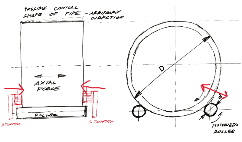
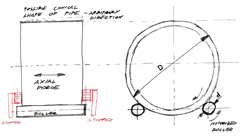
I have a technical challenge, where I need to properly evaluate the axial force of the cylinder (D) rolling on two rollers (d). Data of axial force is needed, because I need to properly design the front and back stopper for the pipe. And because of lack of space (too much to explain here) it is necessary to properly evaluate the force so I don't overdimension the stoppers.

The reason that axial force comes into play is that the big cylinder (D) can be a bit conically shaped. Cylinder (D), in my case, is a pipe with a maximum diameter of 4000 mm and a mass of around 10.000 kg.

Can anyone please point me in the proper direction on how to evaluate this, or have any similar problems known that I can build on?

2024-08-09_14h38_10_znbxpf.png
 
Replies continue below

Recommended for you

The axial force limit is the weight of the object times the coefficient of friction. The only thing that changes with cone angle is the number of times it needs to turn to develop that maximum force against any obstacle you put in the way.
 
3DDave said:
The axial force limit is the weight of the object times the coefficient of friction. The only thing that changes with the cone angle is the number of times it needs to turn to develop that maximum force against any obstacle you put in the way.
Perfect. Thanks for this headsup. Sound logical.

Heaviside1925 said:
When you save conical deformation are you referring to bucking normal to the pipe shell from the compressive force of the stoppers?
No, nothing with pipe deformation. Only moving of cylinder (pipe) front and back on the rollers because of the outer pipe shape being conical - the diameter on one side is smaller than on the other.

MintJulep said:
At the limit, isn't it this?
This I don't understand. Can you please explain the basic thinking behind the equation?

 
Will this conical shape actually roll if the rollers were flat and the big piece D was cone shaped?

The difference in circumference will mean something is constantly slipping so if the weight and CoF is high enough the thing will simply bind up no?

I can't see where this axial force is coming from or what exactly these stoppers are there to do other than locate the big drum on the rollers.

Your rollers would need to be equally conically shaped and at an angle - think tapered roller bearings.
Basically if one complete rotation of the big drum doesn't equal the same number of rotations of the rollers at every point along the drum you're in trouble I think. And axial force will be the least of your problems.


Remember - More details = better answers
Also: If you get a response it's polite to respond to it.
 
What sort of difference in diameter are we talking about here? 0.5 % or 5 %?

Remember - More details = better answers
Also: If you get a response it's polite to respond to it.
 
The limiting friction force would be from normal pressure on the rollers, not weight of the pipe. As the rollers are spread more, axial force increases, I would think.
 
True, but more geometry dependent than expected - for example if one roller was only one degree behind the center and the other was at 90 degrees, the weight would essentially be on one roller. If both rollers were at one degree fore and aft then each would see essentially 50%. The picture looks to be about 30 degrees, but could be some other number. 45 degrees would add 40%; 30 degrees adds only 15%.
 
When a roller or wheel rotates, points on the surface move in a plane at 90 degrees to the axis of rotation. When a cone is in contact with a cylinder it will walk in the direction toward the small end. There will be slippage at all but one point in the line of contact between the surfaces. That point is likely to be under the center of gravity.
To resist this walking, the stop must push back with the force required to slide the roller axially. This force should be equal to the contact force times the coefficient of dynamic friction (dynamic because the surfaces are already slipping while walking). The contact force is the weight of the cone adjusted by the angle from vertical.
I think the logic of MintJulep's argument is also correct.
 
Why is there an axial force?

Musings on the setup - it seems like the cone needs to be supported by tapered rollers. One rotation of the cone should correspond to multiple rotations of tapered support rollers. The cone will rotate uniformly, i.e., one revolution of the big end equals one revolution of the small end. Same for the tapered rollers. If d is the small end cone diameter, and D is the large end cone diameter, then d/D ratio for the cone should also be the tapered roller diameter ratio. Furthermore, the tapered rollers need to be in contact with the cone and this means that they are not parallel. Nothing new under the sun, no doubt this has been solved before.
 
It's not a conical tube. The tube has some random variation in perimeter along its length which most likely will be slightly conical.
 
I agree with the friction comment. One thing I forgot to mention, is that this conical shape is very small, only from tolerances of production errors as 3DDave pointed out. In theory all three axes are parallel, but in real life pipe will travel to one or the other direction when you try to turn it with the rollers. And after it arrives to the stopper it starts to slip and the stopper must push against the friction force. So I will continue from this conclusion.
 
i worked on prestressing machines for concrete pipes (AWWA C301 Lined and/or Embedded - max inner diam 144"- length 6 meters): the stoppers were rubber- rollers touching the front sides of the pipes, but, frankly speaking the forces were, let's say, negligible.
for LittleInch : Same thing if you have a rotating conical mould (Rc poles conical) filled with concrete, but the mould has a set of rollers with same diameters, the concrete will shift to the base of the mould (bigger diam) developping an axial displacement of the mould toward the tip of the mould (smaller diameter). Furthermore, for what said, mould, at beginning, should be filled more in top half keeping in account that part of concrete will slide toward the bottom half. More detailed photos if necessary
 
Jar rolling machines in laboratories are designed to roll jars that are not perfectly cylindrical. The rubber-covered rollers have slight tapers so middle section is narrower than the ends. Jars will stay centered on these rollers without any physical stop required.
 
Status
Not open for further replies.
Back
Top