Hello,
I'm trying to simulate a mechanism on which I have two movements as follows:
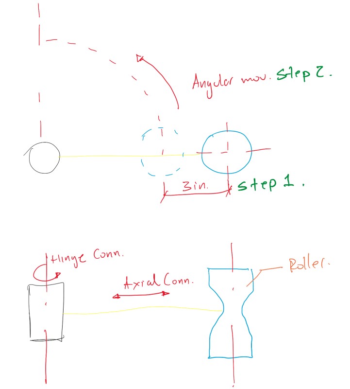
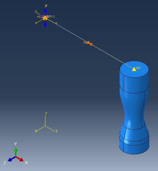
1. Linear Movement in U1 through an Axial Connector.
2. Angular Movement in U1 through a Hinge Connector.
Steps
Step 1 ------------------- Movement 1. -3 inches-
Step 2 ------------------- Movement 2., -6.28 rad- holding the position of Movement 1.
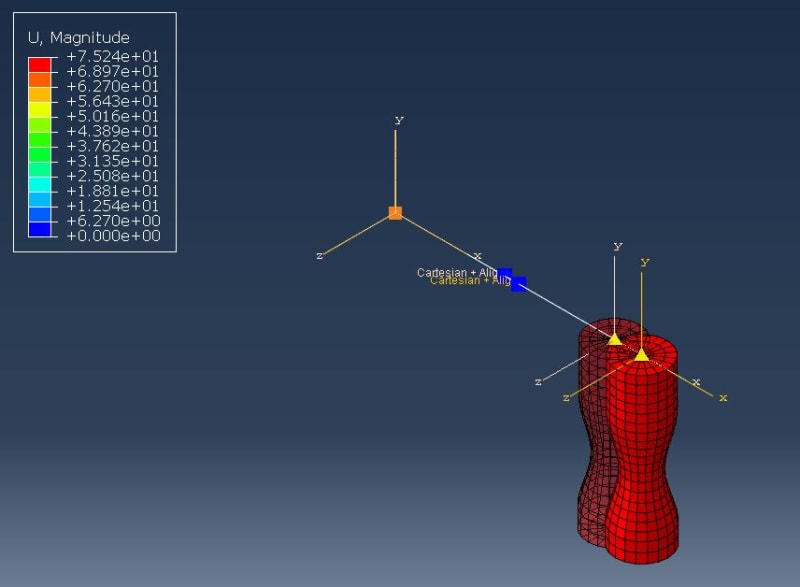
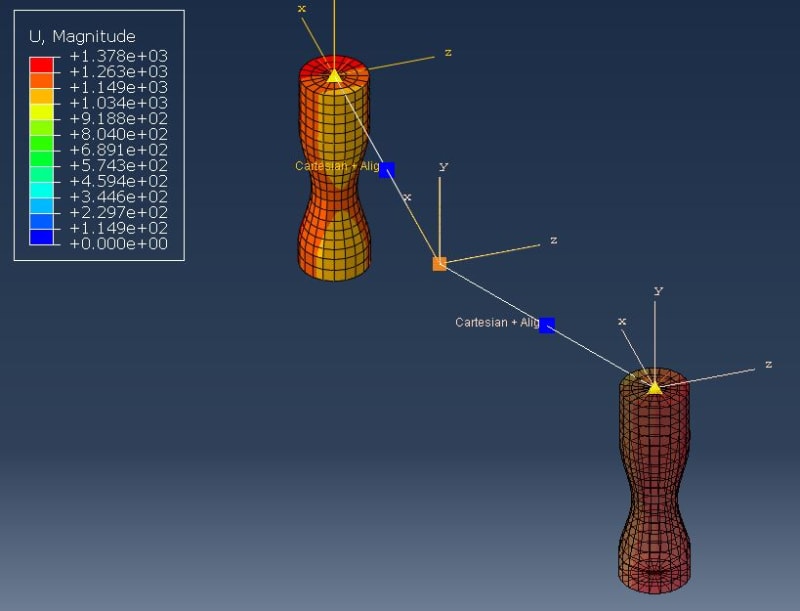
The problem is that if I perform Movement 1., Movement 2. doesn't run or If I perform Movement 2., Movement 1. doesn't run.
I am guessing that my connectors are not set properly.
Any advice will be helpful.
Regards
I'm trying to simulate a mechanism on which I have two movements as follows:
1. Linear Movement in U1 through an Axial Connector.
2. Angular Movement in U1 through a Hinge Connector.
Steps
Step 1 ------------------- Movement 1. -3 inches-
Step 2 ------------------- Movement 2., -6.28 rad- holding the position of Movement 1.
The problem is that if I perform Movement 1., Movement 2. doesn't run or If I perform Movement 2., Movement 1. doesn't run.
I am guessing that my connectors are not set properly.
Any advice will be helpful.
Regards