-
1
- #1
Greetings,
I am attempting an analysis of some experiments in which a hollow tube with non-uniform thickness is loaded proportionally in tension and tosion (such that the nominal axial and shear stresses are proportional).
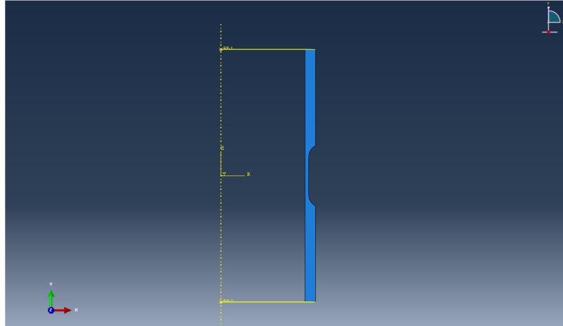
I am using an axisymmetric analysis with CGAX4 elements. Let me describe my model; see the attached image:
X corresponds to the tube thickness direction, Y is the tube's cylindrical axis, Z is normal (out of the computer screen) (see image).
I link both the top surface (with normal +Y) and bottom surface (normal -Y) to its own reference node and create a kinematic coupling constraint. On the bottom, I fix the reference point.
On the top, I permit no translation in X, Z, and no rotation about X or Z. Then, I apply a concentrated force in Y and a moment about Y to this node.
Of interest is the radial contraction of the OD of the structure as it is loaded. Thus, to calculate each node's radial coordinate, I need its X and Z coordinate. In ODB viewer I see that as the model shears, there is displacement in Z. The initially undeformed 2D structure shears in the Z direction under the action of the applied torque, resulting in this Z displacement. However the Z coordinates of every node at every increment is zero!
Can anyone with experience using CG elements explain? Is the Z-displacement I see in ODB viewer meaningless or artificial? Thank you very much.

