B16.47 Question
Greetings,
My Question is 2 parts:
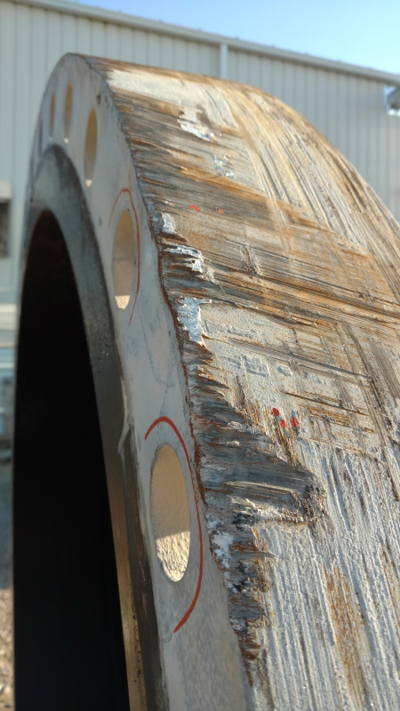
We have a 48" 600# RFWN 44.5" bore SA-350 flange on a unit that was built to the B31.3. The unit fell off of the semi-truck transporting it resulting in damage to the OUTSIDE of the flange. (No flange face damage, just road rash to the outer diameter of the flange)

We have taken appropriate action for all other aspects of the incident but we are deliberating on what to do about the outer diameter.
The B16.47 contains specifications for many of the dimensions of the flange. Using table I-31 Dimensions of Class 600 Series A Flanges we have measured all the dimensions of the flange. The only thing we are coming up short on is the outer diameter "O" where the flange hit. The table references section 7 for tolerances. Section 7 gives dimensional requirements for everything EXCEPT outer diameter. 7.3.1 states tolerances for dimension 'A' but not 'O' and this is for welding ends, not the actual flange outer.
The debate between all parties involved is: do we leave the damage after smoothing out a bit of the road rash, or do we run a sub-arc and build it back up.
Q1.) Are there any tolerances that would govern the damage to this flange? Is there anything specific other than a general 'best practice' on damage/scuffs?
Q2.) If we decide to perform weld buildup, do we then have to PWHT the flange? The unit was originally PWHT'ed per customer requirements.
Any other thoughts or points of concern we have not addressed?
Thank you all in advance.
r/
Greetings,
My Question is 2 parts:
We have a 48" 600# RFWN 44.5" bore SA-350 flange on a unit that was built to the B31.3. The unit fell off of the semi-truck transporting it resulting in damage to the OUTSIDE of the flange. (No flange face damage, just road rash to the outer diameter of the flange)

We have taken appropriate action for all other aspects of the incident but we are deliberating on what to do about the outer diameter.
The B16.47 contains specifications for many of the dimensions of the flange. Using table I-31 Dimensions of Class 600 Series A Flanges we have measured all the dimensions of the flange. The only thing we are coming up short on is the outer diameter "O" where the flange hit. The table references section 7 for tolerances. Section 7 gives dimensional requirements for everything EXCEPT outer diameter. 7.3.1 states tolerances for dimension 'A' but not 'O' and this is for welding ends, not the actual flange outer.
The debate between all parties involved is: do we leave the damage after smoothing out a bit of the road rash, or do we run a sub-arc and build it back up.
Q1.) Are there any tolerances that would govern the damage to this flange? Is there anything specific other than a general 'best practice' on damage/scuffs?
Q2.) If we decide to perform weld buildup, do we then have to PWHT the flange? The unit was originally PWHT'ed per customer requirements.
Any other thoughts or points of concern we have not addressed?
Thank you all in advance.
r/
