Continue to Site

Eng-Tips is the largest engineering community on the Internet

Intelligent Work Forums for Engineering Professionals

  • Congratulations KootK on being selected by the Eng-Tips community for having the most helpful posts in the forums last week. Way to Go!

Backdrilling, or "match-drilling" 4

Sparweb

Aerospace
May 21, 2003
5,131
I'm so used to it that I take it for granted. It's the very common technique for laying out holes in one part and joining it to another one, NOT by laying out holes on it, but by alignment of the two parts, clamping, then drilling through the existing pilot holes from one into the other. This makes well-matched holes in both parts, eliminating misalignment as long as it's done correctly. I could say more about the process but I'm not here to teach it, I'm just getting across what I'm talking about so that my question lands in proper context.

Does anyone know of an industry standard for this process?
-or-
Does anyone know a reputable source that describes the procedure in a manner meant to teach it to personnel, designers, shop workers, inspectors, etc.?

I've checked with the usual suspects (AC 43.13, MIL-specs and MIL handbooks I frequently use, NAS618, etc.) It isn't described in the installation manual for Hi-Loks/HiTigue, despite being pretty important in the hole alignment for those transition-fit fasteners. I had also assumed it would be described in structural repair manuals for various aircraft, but no luck, there, either.
I'm going to get back my copy of Machinery's Handbook (on loan) tomorrow to see if I can find it in there.
For an industry so focused on defining a process for everything we do, I don't believe this should have slipped under the radar - it must be somewhere I haven't thought of looking, yet.
 
Replies continue below

Recommended for you

Interesting question.
Don't think I have ever seen it in any company fastener install process specs.
Might be covered in an internal company fab training course, or maybe in a repair training course.
Have you checked the Abaris training courses?
 
it's more a repair or "mod shop" practice ... OEMs probably won't do it (they can afford high priced tooling).

I'm not sure I'd do this if I had full sized holes in one element ... too much risk of damaging the existing holes.

If I had full sized holes in one element, I'd transfer the hole centers to the 2nd element, open up the holes, then a final ream operation.

If I had two "virgin" plates, I'd pilot one, transfer the pilots to the 2nd, then open up both together.
 
It's been a while, while at convair , if i remember correctly , there was an internal
Manual describing the procedure. You may have write one, with illustrations.
There is an issue, with techs not been trained correctly. We also had mylars with parts drawn to align them . Pilot hole location drawn on the mylar.
 
I have several books...

There are a few newer books dedicated for training structural mechanic/assemblers.

BUT A&P courses at a reputable college are [Spartan, Embry-Riddle, etc] are still the best options for new mechanics... for common basic-skills/knowledge and discipline...

/NOTE1/ in Wichita KS... with multiple aircraft manufacturers... there is a college dedicated to training the skills you are describing... explicitly for the local industry... The National Center for Aviation Training [NCAT]. https://wsutech.edu/aviation/#:~:te...,FAA-approved Aviation Maintenance Technician.

/NOTE2/
I also have several old WWII/1950s aircraft assembly-training books that taught large masses to be competent structural assemblers/mechanics for 1940s mass-war-production... and maybe Korean War.
I'll poke around and see what I can find for new/used purchase. I do have several of the 'older books' scanned/digitized... but they are large files.
The problem is that there are several necessary subjects to co-digest... BEFORE driving a rivet... even in rushed training!
 
Thanks. All of you recognized the nature of this shop skill issue which I'm concerned about. I haven't been asked (yet) to explain all of this but I want to be prepared. It's likely to come up in the next few days, as some conversations about sheet-metal assembly procedures in the shop evolve. I tend not to be concerned with these details, except when the drill is in MY hand, of course. But by now my hands know it better than my head, making it difficult to call up the how and why in words.

A colleague came close today by finding the NAVAIR 01-1A-1 Aircraft structural repair manual. This is one of a series of shop manuals and several of them promise to have detailed shop techniques. 01-1A-8 also looks promising.

Like some of you mentioned, my queries with colleagues also brought up comparisons of how the OEM's do it (e.g. enormous drill fixtures) versus repair shops (e.g. lexan templates). Frankly if I could find a book about either of those processes, or a variety of sheet-metal assembly processes from the shop perspective, that would be great, too

I did look in the A&P handbooks, and while there are hole-drilling techniques described therein, no alignment method is not described. In fact, like all of the sources I'm finding, none of them describe a complete method of securing parts prior to drilling to ensure alignment through the entire drilling and fastening process. When it comes to long rivet joints there are a lot of considerations, and just "going at it" without a plan leads to seams that wander and wrinkle.
 
Wow. I feel like this is one of those Mandela effect situations. I generally think of it as poor practice... but figured someone taught it at some point.

I pulled everything from WWII all the way to every bit of Boeing technician training (that I helped update a few years back), Boeing Process Drilling Sheets... Nothing uses the words "Match drill" that I can find. Even checked Machinery's handbook for you... only talks about larger structural type rivets (think bridge)... talking about holes typically being 1/16 to 1/8 of in inch oversize for swelling... also hot rivets.

My go to is usually MIL-R-47196. When I read it, it certainly has us drilling both sheets at the same time. As do a lot of the Boeing Process Drilling Sheets (PDS####).
However... nothing says pilot drill the top/layout sheet, then final drill to the next. New manufacture has you poking the pilot in both sheets at the same time, then finishing up with a reamer, or piloted double margin drills.

My older book "Nisita" (see below) talks about fitting skins and such... have you lay out "fastener" holes at fairly significant spacing to the tune of 6 inches... but then says to place the rivet holes in them after words... Implied while clamped with no pilot. With modern manufacturing I'd call these tooling or alignment holes. But it's assumed the two sheets are clamped together and both holes are made at the same time.

After searching all of this... I'm inclined to think the term match drilling is from maintenance actions where fitment to existing removed rivet holes is required... which I have to say from personal experience... gage the holes after "match-drilling" as they are almost always blown out in some form of out of round. When rivets get removed I find that the hole is expanded a little from the original rivet installation is my guess. If I remember off the top of my head a #4 is drilled .125 to .135... and I often see holes right on the edge of .135 to .138 after rivet removal. Very common to see #3 blown out well up to .110".


Refs:
-------------------------------
MIL-R-47196 (used for new manufacture)

3.2.1.1 Drilling....
a. All holes shall be shall be drilled normal (at 90 degrees) to the working surface.
b. Extreme pressure shall not be applied and holes shall not be punched through with the drill.
c. When drilling through more than one sheet, hold the sheets securely together so there is no misalignment of holes due to shifting or separation of the sheets.

3.3.1 Cleaning mating surfaces. Before parts are riveted together, all ships, burrs, and foreign material shall be removed form the mating surfaces. Burrs may be removed from rivet holes by chamfering to a depth not to exceed 10 percent of the stock thickness, or 0.032 inch, whichever is less. Disassembly after drilling and before riveting, in order to deburr faying surfaces shall not be required.

4.2.1 Defects
g. Sheet separation after riveting which allows a 0.002 inch feeler gage to be inserted between sheets from any direction far enough to touch rivet shank.
n. Deformed skin or open seams caused by pressure on rivets.
o. bulging skin caused by expanded skin or trapped chips.
---------------------------------
TM 1-1500-204-23-10 (maintenance guidance)

7-4 (c) Riveting Procedure...
(1)(a) Hole transfer. Accomplish transfer ofholes from a drilled part to another part by placing second part over first and using established holes as a guide. Using an alternate method, scribe hole location through from drilled part onto part to be drilled, spot with a centerpunch and drill.
(1)(b) New sections. In areas involving complete new sections, drill from skin inward into stringer, or drill from stringer outward. In either case, first drill0.098-inch pilot holes in member nearest operation, locate and attach second member to first by two C clamps or spring fasteners; size-drill through both members, separate sheets, and remove burrs from holes.


8-8 Skin Replacement and Repair.
a(5) (a) Back drilling, using the holes in the reinforcing members as guides, and installing occasional Cleco fasteners as described in paragraph (4). The reinforcing members must be aligned and flush at the points where they intersect; otherwise, the holes in the new sheet will not be accurately aligned. For the same reasons, the new sheet should have the same contour as the old one before the rivet holes are drilled. The skin must also be held firmly against the framework while drilling. This can be done by placing a block of wood against the skin and holding it firmly while drilling.
-------------------
Aircraft sheetmetal assembly by goodyear aircraft 9/23/1942 (new manufacture). Doesnt mention it AT all. Not even the shop project instructions.
-------------------
Aircraft Riveting by Albert H. Nisita. Also September 1942 (new manufacture)

Small areas
1. If the material has not been previously prepared, it should be clamped before drilling.
2. lay out all dimensions lines and the location of all holes on the top sheet only. ***<---- that I totally understand and agree there is no point to lay out the second sheet.**

End to end method (some paraphrasing here)
Skin creeping is bound to occur in jobs unless holding the material tight is used. Fasteners are installed at one end and the subsequent sheet holders installed in proper sequence in one direction. Apply fasteners immediately after drilling until the sheet is completely tied down to the stringers or bulkheads. To apply fasteners too far apart, or at each end first, and then at intermediate stations in a long installation causes the skin to buckle or gives it a "wavy" appearance. This condition is caused by trapping the surplus skin between the end fasteners and by not allowing the surplus material to move out toward the edges. Do not tie the edges or joints down first. fasteners must be applied immediately after drilling the hole or holes, depending on the nature of the installation.

Center method

Fasteners are installed first in the approximate center of the sheet and then equally spaced toward all edges. The slack is removed as evenly as possible. This method if properly employed will result in drum-tight installation which is necessary before the rivets are installed.
-----------
I have another book for sheetmetal teachers that is Racist as it gets... but has great info otherwise I cant seem to find... maybe for the better.
 
R...

The term 'match drill' should be used only when all-parts are pre-drilled to exacting tolerances with undersized holes that allow a degree of jig/fixture-less assembly with clecos, or other tight-fitting temporary fasteners etc. The assembly is THEN re/final-drilled to nominal-sized holes and held rigidly by larger-temporary fasteners, as this process proceeds... until permanent fasteners are installed are installed 1-at-a-time using a typical cross-pattern sequence. All-metal 'kit' homebuilt aircraft are trending to this method of 'for fast Assembly'... with different degrees of success.

My dad's built his 1960s era Thorp T-18 homebuilt this way. The designer laid-out precision hole patterns [x.xxxx-tolerances] that were transferred to precision templates by a master tooling guy. These precision templates with pre-piloted holes were used for every sheet metal parts on the aircraft... successfully! My Dad/I simply scribed around the templates, then center-punched [by pointed-tip-punch/light-hammer]... on a raw piece of sheet metal.

We then drilled-out the holes #40 and cut around the outline and deburred every sharp edge. Ta-Da a ready-to-install part [still needed primer]. With all the parts 'at-hand' we then proceeded to 'Cleco' all pieces together [using undersized Clecos matching the undersized predrilled/punched-holes in both/all parts]... to 'almost magically self-assemble the structure without jigs/fixtures'.

Then we re-drilled every hole to nominal and either Clecoed-to-nominal... or installed nominal rivets as-we-went. IF 'Clecoed to nominal', we-then installed rivets in the open holes, after-which we removed the remaining clecos and installed rivets in those. We typically Clecoed every-2nd or 3rd hole [depending], to retain precision alignment for final fastening. We usually assembled major areas of structure with Clecos... unless we ran-out of Clecos... then we sometimes used soft aluminum blind-rivets... easily drilled-out.. in every 2nd or 3rd hole to help finish the Assy.

NOTE: When using any temporary fastener [Clecos] with this method, usually NOT every hole was fastened... usually every-2nd or 3rd hole actually needed to be Clecoed to retain acceptable alignment [judgement].

Unfortunately a LOT has to be understood about this process to 'do-it right'. I heard recently that VANs RV Acft tried to do this with nominal laser-drilled holes... that had laser-star-holes OUTSIDE OF THE NOMINAL HOLE DIAMETER... had major problems with cracking on Assy.. and in-service. Corrective actions/restitutions... almost bankrupted the company

xxxxxxxxxxxxxxxxx

OK... here is where original structure Assys are rebuilt with modifications or repairs. Repair or mod parts are to be installed on original structure parts/Assys [A]... and fastened-thru holes in existing structure [A]. For this process of drilling -to-mate with-[A] I prefer/use the most accurate term 'mate-drilling'.

/WARNING/ Sloppy/non-standard disassembly methods... fastener removal, prying, etc... which can damage/elongate the original holes and structure... are a nightmare. Structural disassembly [fastener removal] 'by the book' can usually make the process of integrating repair/mod parts relatively easy... BUT when done with no regard for 'best fastener removal processes' and structure-support/separating' procedures [especially 'sealed structure]... the reassembly work can be freakish/mindboggling difficult. UNLESS NO ONE CARES. Proper fastener removal is a whole different topic.


Reassembly.

'Clamp/hold' new parts to old in-alignment. Drill thru to 'Nominal/existing diameters'. Then since NO mate-drilled holes will be 'perfect/acceptable' when drilled to 'nominal matching existing hole sizes... NEVER-EVER... ALL mate-drilled holes MUST always be 'stepped-up' at least 1/64-Oversize [1OS] or perhaps 2/64-Oversize [2OS] depending on condition as-disassembled. This OS process actually does [2] 'good-things' in one fell-swoop... [1] produces cleaner-rounder thru-holes in the 'stack-up' for improved new-fastener fit... AND [2] the OS drilled/reamed hole is 'purged' [cleaned-out] of minor [microscopic] damage' in the original hole wall, such-as corrosion, roughness, burrs and micro-sized cracks in their earliest stages of initiation... and usually allows a 'reset' in fatigue life for that fastener location.

Then, in-theory... not always in practice unless made strictly mandatory in BOLD PRINT... eddy current inspections for any detectable remaining defects in original- or new- part holes validates elimination of NDI-detectable defects.. At this point the structure is ready for re-assembly 'by the book'.

God I am tired. Hope these Scribbles from an old-guy make sense.
 
all very helpfull Will;
there are so many variables and situations,
one could write book; and not cover it all.
then there is old school and current technology. Manual match drilling vs automatic drill and rivet.
there are situations that there are no pre drilled number 40 holes. and there are cases where the top sheet metal part requires it.
assembly fixtures vs assembly drill jig fixtures.
match drilling to insure edge distance is maintained.
I fiquire there is new tech and methods then in my time.
 
You want to see some incredible stuff... visit Gulfstream in Savannah. The "panels" or "units" (I forgot what they call them) that they make on those giant machines that literally do everything is straight out of star wars.
 
TM 1-1500-204-23-10 (maintenance guidance)
That's what I was looking for. Thank you!
Manufacturing has been asking to use this process recently. I have been giving requests a "fair hearing" even though the other engineers around me are climbing the walls with objections. The requests are coming from personnel in our plant not quite equipped to do their own research, and didn't have anything like this to offer in recent discussions. I could bat them down because they aren't doing their homework, but I didn't like it when I was in school. Instead, I wanted to have a look for myself, at what kind of rigor these procedures can be given. Answer: some, but it's all clearly been developed as the "low-tech" solution to sheet-metal assembly. Exactly what I want to get away from!

I'm trying to get my crew comfortable with using fixtures, and tooling with more control. But it's a long uphill process that I've inherited. These folks have never even seen a spacematic drill, let alone a CNC gantry drill like you've mentioned at Gulfstream. I got to watch the one at Bombardier operate one afternoon, yeah.
 
Fantastic. Glad to do something helpful!

I'm glad you brought this up. Making me rethink how I do some stuff.
 
Ah yes... MIL stuff...

TM 1-1500-204-23-10 AVIATION UNIT MAINTENANCE (AVUM) AND AVIATION INTERMEDIATE MAINTENANCE (AVIM) MANUAL - FOR GENERAL AIRCRAFT MAINTENANCE (SHEET METAL SHOP PRACTICES) VOLUME 10 https://aviation-assets.info/wp-content/uploads/tm1-1500-204-23-10-sheet-metal-shop.pdf

SUBCOURSE EDITION - AL0992 A BASIC AIRFRAME REPAIR

TO 1-1A-1 TECHNICAL MANUAL ENGINEERING HANDBOOK SERIES FOR AIRCRAFT REPAIR - GENERAL MANUAL FOR STRUCTURAL REPAIR

Old books... illustration only...


*FAA-H-8083-30B, Aviation Maintenance Technician Handbook – General (PDF 91 MB)
*FAA-H-8083-31B, Aviation Maintenance Technician Handbook – Airframe (PDF 110 MB)

AC 43.13-1 Acceptable Methods, Techniques, and Practices - Aircraft Inspection and Repair

AC65.15 Airframe & Powerplant MECHANICS - AIRFRAME HANDBOOK

MSFC-STD-156-RevA1 Riveting, Fabrication & Inspection -Standard for

Aircraft sheet metal construction and repairs for aircraft mechanics and sheet metal workers, Hardcover – January 1, 1942
 

Attachments

  • Riveting for Beginners in Acft Metal Work~UNY Course~1941~xx.pdf
    43.9 MB · Views: 9
And... The end.
 

Attachments

  • Aircraft Riveting~AH Nisita~1942~OCR.pdf
    18.9 MB · Views: 6
there are very good YouTube videos as an aid to engineering , techs.
 
here is one depicts the drilling.
but I would use # 40 pilot holes to verify edge distance firsts. on the periphery
 
In my experience, match drilling and it's counterpart match-forming are generally not specified in much detail on a repair plan / repair instruction or installation instructions. As a stress liaison / repair engineer you learn to tow a balance between being specific enough in your instructions that you can fully define the configuration for things like F&DT purposes or compliance, yet leaving enough leeway for the skilled mechanics to "figure it out". There can be a fine line of over-constraint where they are going to stop on work steps where they shouldn't have to.

Things like match drilling tend to be in the area where we let the A&Ps do what they do. So in addition to the manuals Wil provided, etc. I would expect an A&P instructor could provide you with more explicit detail from a course.

Even in OEM structural repair manuals, these details are left fairly vague. Not even a reference to an SOPM section. For example, here are some of the notes I can recall:

Make sure that you meet the conditions that follow when you make and install the repair parts:
A) Pre-form or roll the repair parts to match the fuselage skin contour before they are installed. Reverse forming is not permitted.
B) Localized forces may be used to assemble the part to the fuselage within the limits that follow:
1. A finger pressure of up to 2 pounds can be applied at a minimum of 12 in. (305 mm) intervals for part thicknesses less than 0.045 in. (1.143 mm).
2. A finger pressure of up to 5 pounds can be applied at a minimum of 12 inches intervals for part thicknesses of 0.045 in. (1.143 mm) and greater.
NOTE: Gaps of 0.010 in. (0.254 mm) or less can remain after the application of the limited localized force. You can close these gaps when you install the fasteners, or you can apply additional clamp force as necessary before fastener installation. When you close gaps between parts, make sure that the assembly meets the configuration requirements before you drill fastener holes or install fasteners.
C) Shim all gaps greater than 0.010 in.

Assemble the repair parts and drill the fastener holes. If an external plate is being replaced, drill fastener holes in repair part to match initial holes in the skin. Otherwise, drill fastener holes according to the fastener pattern shown.

If a repair is picking up existing fastener holes they would be O/S by at least 1/64th in.

An example of a match drilling callout from a Service Bulletin where it is required:

Match drill the fastener holes on the new stringer 1 fitting that is common to the Aluminum T-Chord and the Upper Panel. Boeingrecommends using an undersize drill bushing in the existing full size holes in the Aluminum T-Chord and Upper Panel structures totransfer holes to the new stringer 1 fitting. Clamp fitting to structure as required during this process. The undersized holes in thestringer 1 fitting can then be drilled to the full size off of the airplane on an appropriate machine fixture. It is also permissible to usea jig bore process to transfer holes from the removed stringer 1 fitting to the new stringer 1 fitting. Oversizing of holes is not allowed.Refer to SOPM 20-50-01 as an accepted procedure.

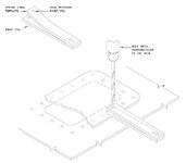
Occasionally we we see the use of what's called a "hole finder" for matching holes to new parts. This was a mechanic fabricated device something like this:

2024-12-12_16-23-32.jpg
 
That only works when there are techs with years and years of experience. We can't hold their hands. This is to properly train new techs as well as engineers. Who are green.
As well having leads who have proficient experience. I have seen were companies tried to out source. And it failed caused scrap.
 
Wil,
You never fail to turn up fascinating historical detail. The two manuals from the early '40s make for interesting reading, far beyond my current interest in back-drilling procedures. Look how far evolved their hand-held drills and rivet guns were then. Jacobs chucks and Cleco clamps.

I'd have a lot of fun hearing a MRB proposed rework if it was based on page 42's method to "shrink" a hole drilled oversize!

Note the student project drawings at the back (page 153). I was looking for something like that a couple of years ago. Ended up drawing something myself, a lot like it. Had several interns make some riveting project parts so that they could grasp the process.
 

Part and Inventory Search

Sponsor