Eng-Tips is the largest engineering community on the Internet

Intelligent Work Forums for Engineering Professionals

Balancing ring gear, formed flexplate and timing locator

Status
Not open for further replies.

Dobe

Mechanical
Oct 1, 2003
51
0
0
US
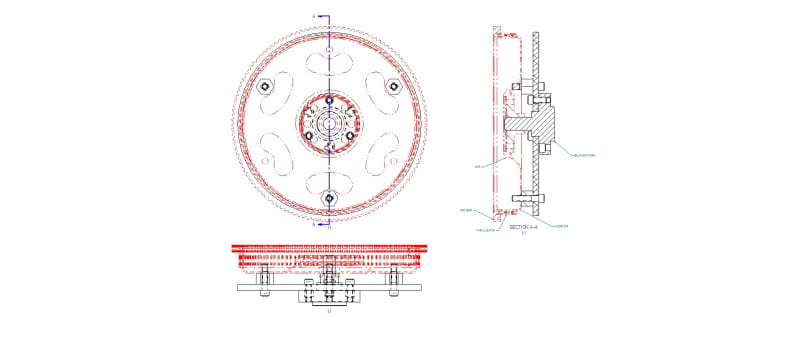
I have a weldment of the above parts and cannot get the balancing below .5 or below 1.
We weld the flexplate to the ring gear first in a fixture. 2nd fixture welds the 1st 2 components to a hub.
and then we weld the timing locator ring in the 3rd weld fixture. We are getting 2.41-2.61 for balance.
Any conversation about this will be greatly appreciated. Anyone do any balancing with 4 components and 3 weldments?
 
Replies continue below

Recommended for you

The number "1" means nothing without units ...

I suspect you are dealing with automotive parts.

I've seen something similar to this, and the process sends the assembly through a specialized balancing machine. IIRC one of the parts has designed-in tabs on one of the parts that are designed to have a variable amount machined off in order to balance the assembly.

Crankshafts often have blind holes drilled into some of the counterweight webs. That's also for balancing. The depth of that blind hole varies in order to balance the assembly.

Tell us how your balancing process works.
 
We have a balancing machine. We mount a fixture that uses a center plug to keep the weldment concentric.
The machine/fixture is setup or calibrated with the weldment 3 times before actual balancing is initiated.
We balance several other ring gear/flexplate weldments, but none with this many components welded together.
Print balancing spec is 360 g/mm
 
So what is the issue?

Is the problem with a raw weldment?

Is the problem that despite designated machining being done to balance the part, it still doesn't balance even after that having been done?
 
I have define the balancing strategy for a couple of engines. I can't understand the numbers in your first post at all, and the units in your last post are probably g mm not g/mm.

For a production engine we used to rough balance the crank casting (so that we could run the lathes at a reasonable speed), balance the finished crank, balance the flexplate, assemble the engine, balance the complete engine.

Cheers

Greg Locock


New here? Try reading these, they might help FAQ731-376
 
You are correct on the numbers 360 g mm. Is the g for grams and the mm is metric? Maybe I'm not reading correctly.
Our company only makes the flexplate/ring gear weldment. I have no access to the crankshaft or engine. I believe this is going into a UTV.
So I worked on balancing each component separately and they balance .31 - .36.
The flexplate is out concentricity .020. flatness runs .014-.022.

The original design had 10 welds flexplate to ring gear. The customer wanted that changed to lighten it up, so we now have 5?
The center hub to the flexplate was welded all the way around, that was changed to 6/1" welds.
Then there is the timing locator welded into a machined slot in the ring gear that had 10 welds, but also changed to 5.
I've tried to keep the welds symmetrical and the same length using a weld locator plate in the fixture, but not sure if it matters how many welds, odd number like 5 or even number like 6?
 
Balance_do_not_use_ktso2m.jpg


For those helping me here is a pic of the weldment on the balance fixture.
 
Dobe said:
You are correct on the numbers 360 g mm. Is the g for grams and the mm is metric?

yes, grams and millimeters.

Dobe said:
So I worked on balancing each component separately and they balance .31 - .36.

Units? Compared to 360 g-mm that sounds like it's ok.

Dobe said:
The flexplate is out concentricity .020. flatness runs .014-.022.
Is that before or after welding? Sounds like a problem regardless - can you straighten the mis-flat parts and machine to adjust for the concentricity errors? Are the parts fixtured when welding, and can you run the parts with tighter location features (eg a set of tapered pins to lock parts into the mating holes) to lower the concentricity error?
 
Flexplate dimensions above are b4 weld.
Yes, we are looking in to using machining to correct. The out of flat problem I'm not sure of yet. The flexplate comes out of a die, which needs more work to correct some problems.
Right now the flexplate is held by the machined hub on a center post. I have 3 standoffs that the flexplate is on and bolted down.
 
Status
Not open for further replies.
Back
Top