Continue to Site

Eng-Tips is the largest engineering community on the Internet

Intelligent Work Forums for Engineering Professionals

  • Congratulations KootK on being selected by the Eng-Tips community for having the most helpful posts in the forums last week. Way to Go!

Band Tubular Weld Lap Joint Fillet Weld

Status
Not open for further replies.

shorion

Mechanical
Nov 5, 2013
29
Hi all,

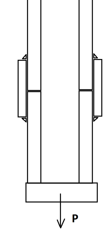
Trying to chase down design calculations for stress in a 'band' joining two pipe lengths together.
Stress in the weld.
Stress in the pipe (because its going to be in torsion as the load tries to pull the welds into the pipe)

The pipes are butted up to each other. The band is lap welded around the full circumference.

Pipe hangs vertically from the roof and supports a 1/2 ton load.

A cross section of it looks something like....
a_ccoi7q.png


I told them to fully butt weld
Use a single piece
Or taper and weld

Think of a designer fireplace that hangs from the ceiling with no support at the base and you will get the idea.

They want what they want I guess.

I have a few figures down already but would like feedback on how others approach it, standard equations from reference material etc.

Thanks in advance!
 
Replies continue below

Recommended for you

I'm not clear on what you think the problem is with the sketched detail? It seems pretty reasonable. Your weld is basically in pure shear assuming your pipe wall isn't incredibly flimsy, you have a tiny bit of moment in the pipe/sleeve wall from the eccentricity but because it's a closed section it can resolve in ring tension/compression and shouldn't be an issue. You obviously have a load path for tension, but you also have a reasonable amount of rigidity from the moment capacity of the closed circular weld.

If you really want to check the wall bending from the eccentricity, there are fomulas for it in Roark's if you don't want to try and work it out yourself. I probably wouldn't bother if the wall thickness of the pipe is anything reasonable and the load is small.

You have no overall eccentricities on the section as a whole, since your center of resistance is constant through all the various sections as you travel downward.

 
Agree with TLHS...just a direct shear calculation for sizing the weld.
 
Be careful when nesting two pipes inside each other. They typically do not mate together 100% due to the actual OD and ID of the respective pipes. As such, you may be left with a gap between the pipes and end up with what Duane Miller of Lincoln Electric refers to as a "Nothin' Weld"......essentially where the weld bridges over an unintentional gap between pieces.
 
"joining two pipe lengths together"

What size?

Pipe, like from Home Depot plumbing department?
I'm not sure the material certs are available, thus the weldability may be worth questioning.

With the dimensions (proportions, really) shown I'd expect the spliced pipe will be kinked to some degree without careful attention to fixturing and weld procedure

Designer fireplace - designer pipe? Stainless steel, copper or brass?
Will the welds be ground to become designer welds?

I'd be thinking about the attachment at the ceiling, and planning to NDT the welds, just in case. Maybe even A 4x proof load test as well

I wonder if a few strategically placed pins could be installed radially thru the coupling and pipe, and hidden under an I-watch or timepiece from A.Lange & Soehne slipped into position.
 
Shorion:
You said... “Think of a designer fireplace that hangs from the ceiling with no support at the base and you will get the idea. They want what they want I guess.” Who’s the engineer on this project anyway? You should be giving them good sound engineering advice, not just trying to design around (to meet) the client’s silly/bad ideas. Obviously, you should be able to explain your reasons for your suggested changes/improvements, they should be to improve final appearance, safety/strength, constructibility, etc.

It seems to me that there are bigger design issues than that ugly pipe splice detail, you did say ‘designer fireplace,’ right? That joint will stand out like a sore thumb, on hangers which should be light/slender and clean. A simple CJP or PJP butt weld, with an inner back-up and alignment bar will look much cleaner and probably be less expensive too. While your sketch shows these proportions, I’ll bet the pipe wall thickness is thinner than (.2)(pipe dia.). You don’t bother to show any approx. dimensions, sizes, thicknesses, etc., but for a 1 kip/hanger loading, a .75" or 1" round bar would be more than adequate. A ground down (cleaned up) butt weld will work here too. What are the connection details going to look like at/under the fire box and at the ceiling structure? Can the roof structure carry this concentrated loading?

What is the vert. dimension btwn. the floor, the hearth elevation, and the hanging structure at the ceiling? This fireplace is going to be hanging there like a pendulum, and a couple 300lb. linemen will sit on the hearth, at a drunken party, and try to use it as a swing, and add another 600lbs. to one hanger also. Can your hanging system take this type loading, or what are you doing to manage these loads? How are you venting this fireplace through the roof, and providing combustion air? A fireplace which is open all around takes a very large exhaust flue to vent properly. All of these various items/conditions can not tolerate much/any lateral movement of the main fireplace box/enclosure. What are you doing to handle this situation?
 
Status
Not open for further replies.

Part and Inventory Search

Sponsor