Continue to Site

Eng-Tips is the largest engineering community on the Internet

Intelligent Work Forums for Engineering Professionals

  • Congratulations SSS148 on being selected by the Eng-Tips community for having the most helpful posts in the forums last week. Way to Go!

Barrel Hinge - Design Resources?

Status
Not open for further replies.

JoelTXCive

Civil/Environmental
Jul 24, 2016
933
Hi there.

I am designing a screened steel gate for pump station. The gate is 8ft wide by 7ft tall (they want to drive a bobcat/small tractor into the pump station to clean the crud out after a major storm event).

95% of the time the gate will be dry, but in flood events, water will flow through the gate and into the pump station. If debris gets hung up on the gate then the gate will be subject to a significant lateral load. As of now, the hydraulics people are telling me to assume 10ft of static water head on the gate if it gets clogged up.

I'm looking for off the shelf hinges, but I think I am at the extremes of what is available. I'm looking at factored loads in the neighborhood of 2,500 to 3,000 lbs per hinge.

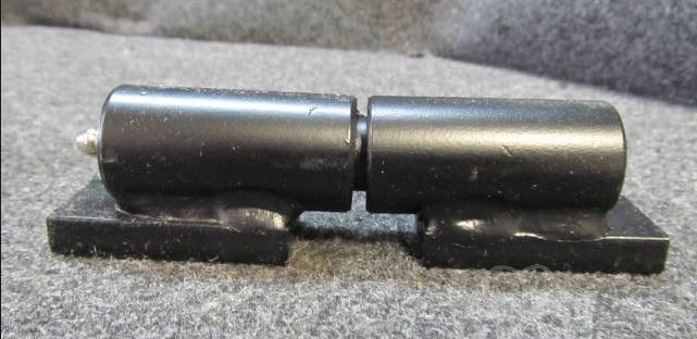
Maybe i can design my own piano hinge or barrel hinge?

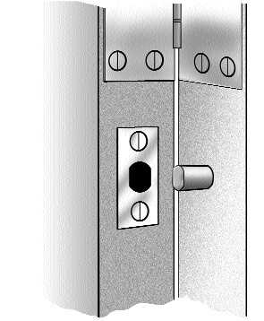
Does anyone know of some good design resources for this? I've googled, but not come across anything. (below is an example photo of what I am thinking)

Thank you.

Barrel_Hinge_dyzwua.jpg
 
Replies continue below

Recommended for you

Perhaps you can design it so that the gate frame closes onto steel shear pins set into the concrete/steel support structure. That way the hinges do not need to be rated for the hydrostatic load.

Edit: Basically this is the idea used to protect security door hinges. You might need to design for some movement in the hinges so that the pins are loaded.

lock_door_hingebolt.jpg
 
JoelTXCive:
You might be better off making two half gates 4.5’ wide, the hinge loads will be smaller, and you don’t need 8-9’ in front for gate swing. Put a sliding pin down into a pc. of pipe in a conc. ftg. at the center on one of the halves, and a lock and hasp on the other half. Most of the time you will likely only be opening one half of the total gate, for maintenance, etc. It would have been nice if you had put some dimensions, sizes, etc. on the photo of the hinge you have, to give some idea of the proportions of what you are thinking of. If I were to do something to the hinge you show it might be to weld a couple hardened washers to the large pipe halves, at the parting line. This would provide an improved bearing surface and bearing/wear stresses. There are also several wear/friction products (FiberGlid is one, Google it) which significantly improve the gate swing friction, and can be purchased as washers, to match the hardened washers in o.d. Then, grease would probably not be required; it just collects dirt and likely won’t get done anyway. A 7’ high gate should not often see 10’ of hydrostatic pressure in a flood, and the bottom hinge will see higher pressures and forces, so watch out for that. Then, the primary design consideration is the shear and wear of the moving pin btwn. the two hinge halves. The pin can be press fit into one of the pipe halves and has a few thousandths clearance in the other.

 
JoelTXCive:

Take a look at these products from Guden:

Link

I'm sure they have, or can make hinges to meet your needs. No point in reinventing the wheel here.

Regards,

DB
 
Thank you all for the input.

I am going to see about putting a removable post in, and then doing a double gate to cut the span. The gate will be covered in steel grating, so my self weight is high. Throw in the lateral load from the 10ft of water and the hinge loads get really big.

As of now, we are doing a uniform distribution of 624 psf (10ft *62.4pcf). This is not a triangular pressure distribution that you would normally see with water. The 10ft of head value is an arbitrary number that the water engineers have provided as a guide. They are worried about debris impacts and clogging.

Attached is a conceptual video showing the setup of the pump station. At full flow (Noah's Ark loading condition), they will be pumping 270,000 gallons per minute through the structure.

Link

Below is a photo showing the location. The clear opening is 7ft wide. I wanted my gate assembly to be 8ft wide so that the gate is larger than the opening. Then, in a failure situation, you will have to crush the gate to suck it into the pump area. I'm also able to shed lateral load to both sides of the gate.

I'm open to any other input.
Thank you.
Pump_Station_Gate_uzsh2g.jpg
 
Status
Not open for further replies.

Part and Inventory Search

Sponsor