Continue to Site

Eng-Tips is the largest engineering community on the Internet

Intelligent Work Forums for Engineering Professionals

  • Congratulations KootK on being selected by the Eng-Tips community for having the most helpful posts in the forums last week. Way to Go!

BASIC MIN /MAX CALCULATION- VERY BASIC

Status
Not open for further replies.

appvid

Automotive
Nov 9, 2012
81
[URL unfurl="true"]https://res.cloudinary.com/engineering-com/image/upload/v1652746102/tips/GDT_question_1_itbqwf.pdf[/url]


Hello All, Good Evening
I just want to start with a very basic question. I would like to use the excel file to find my Min /Max Values. I have downloaded that excel from this forum.
I want to start with your guidance rather assuming something wrong
.

Then I would like to figure out myself on shift and bonus when I get fundamentals right. Appreciate your help

Please see attached.

 
Replies continue below

Recommended for you

You asked when to use the + or - in the Max (or Min) column. That depends on the direction that the vector is traveling in your "stack path." So before filling in that spreadsheet, you should sketch a starting point and an ending point to the distance you are solving for, and then sketch some vectors to get from start to finish. ((Within those vectors, you sometimes also have position tolerances, along with "bonus" or "shift" tolerances.)

However, the sketch you provided won't have any bonus or shift; it just uses traditional ± distances between the 2 holes and 2 pins.

So your question is a little more involved... We'd have to give you a crash course on tolerance stack analysis. But the main answer is that the + and - numbers to fill in depends on having a path of connected dimensions.
 
The answer to your question depends on what "minimum diameter" means. The following should allow you to work with whatever definition you like.

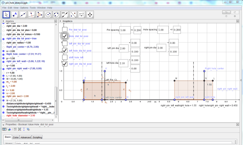
I have a GeoGebra file attached that lets you work with this problem. I have scaled the majority of the dimensions down by a factor of 10 and reduced the spacing to better fit on the sheet.

The check boxes select the various conditions:
1) Sets the pin distance position tolerance to positive, else it is negative
2) Sets the hole distance position tolerance to positive, else it is negative
3) Sets the left pin diameter size to use the positive tolerance, else it is set to the negative one
4) Sets the left hole diameter size to use the positive tolerance, else it is set to the negative one
5) Sets the calculation as if the left hole is pushed to the left against the pin, else it is pushed to the right
6) Set the right pin diameter size to use the positive tolerance, else it uses the negative one

At the bottom of the list is the expected hole diameter for the right end hole.

GeoGebra is available for free from The file I created is from GeoGebra Classic 5 for Windows. See for Classic 5 and Classic 6.

It looks like:
pin_hole_analysis_sucwwr.png


The right side hole diameter is marked in red.

If a change is made that breaks the diagram then just reload from the one I posted. For no reason it sometimes evaluates the results as true/false rather than numbers. Maybe they fixed it in Classic 6. Anyway it's free, so you get what you paid for, a bargain at twice the price.
 
Thank you Belanger

Please see attached. I have gone through several threads and got an idea on how to use excel file. Brain started to explode but managed to make some progress since morning.
1- Is my chain dimensions correct??? ( A to F). Do you see any errors. Regards

[URL unfurl="true"]https://res.cloudinary.com/engineering-com/image/upload/v1652828503/tips/Please_check-_thank_you_kix5fj.pdf[/url]


3D DAve

Thank you let me download and go through your instructions. Looks' interesting.
 
Status
Not open for further replies.

Part and Inventory Search

Sponsor