Continue to Site

Eng-Tips is the largest engineering community on the Internet

Intelligent Work Forums for Engineering Professionals

  • Congratulations SDETERS on being selected by the Eng-Tips community for having the most helpful posts in the forums last week. Way to Go!

Beam at cast-ins 6

Status
Not open for further replies.

Veer007

Civil/Environmental
Sep 7, 2016
379
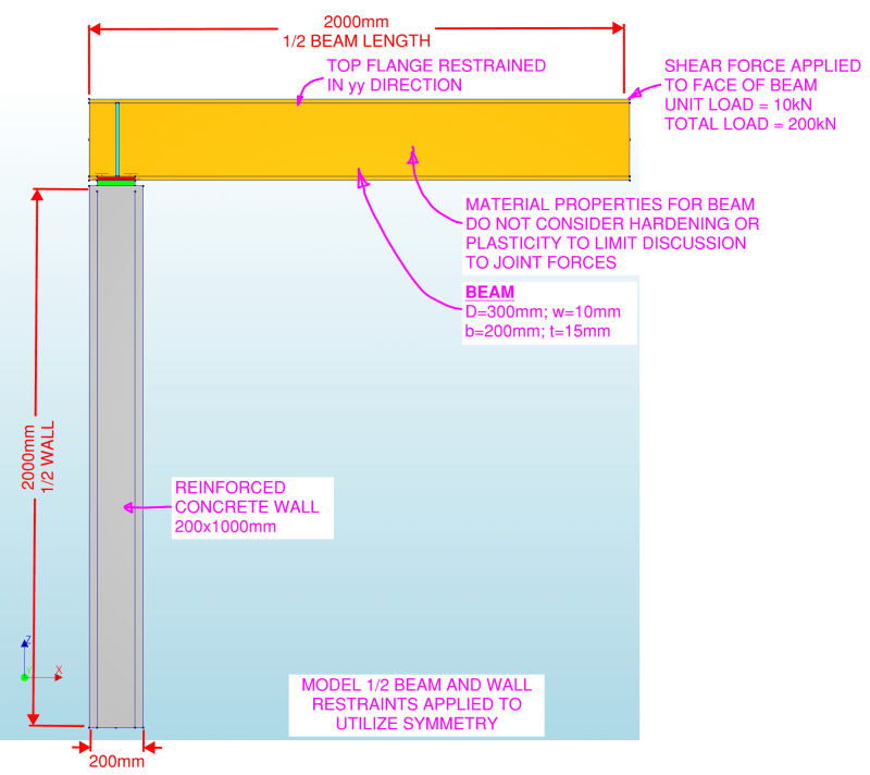
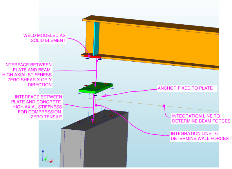
Hello guys, Please refer to the snap below, which option actually seems correct as I'm worried about beam slopes at the end if I weld a beam and cast-ins?
bmbearing2_pylbp6.gif
bmbearing4_sgftry.gif


Thanks in advance!!
 
Replies continue below

Recommended for you

The one on the right is more common in my experience. It provides more 'fudge room' in case the anchors aren't placed perfectly. You can either shop weld it and use slotted holes which gives adjustment in one direction, or field weld it and the plate can be set with wither anchors as shown or with headed studs welded to the bottom. That gives adjustment in all directions and the beam can be set precisely and welded into place.
 
Thank you Isn't it an issue if we weld a beam with cast-ins when we have a larger span that beam deflects at mid.

Thanks in advance!!
 
Is what an issue? All beams deflect and have rotation at their ends. What are you concerned about here?

Also, and I'm sure it's just excluded for clarity, but you will have the required full height stiffeners over bearing for this connection or other suitable torsional restraint at the beam end, right?
 
Yes, I agree and I will have to add a stiffener at the beam end, Just curious about how we will deal with the end rotation (below snap shows), apologies if this may sound silly
image_z2bczv_orx2rw.png


Thanks in advance!!
 
If the beam end is meant to be a "pin", then I've never had a case where it was of particular concern. How much rotation are you expecting?
 
I didn't calculate any specific values, I was just wondering if there was any chance the welding would be affected

Thanks in advance!!
 
In a beam that's been properly sized for strength and serviceability - the answer will almost always be not enough to worry about. It will produce some end fixity and you will have stresses in the weld, but it's unlikely to be an issue. And all of that is there even if it isn't welded - it's just direct into the anchors.
 
1) I've used a rocker bar detail like shown below in the past when I've been worried about this.

2) For most beams, I'm sure that this isn't a concern and that some measure of weld "protection" is gleaned from:

a) Beams sized to common deflection limits and, therefore, end slopes.

b) The ability of the flange at the support to flex a bit between the weld and the beam web.

3) I've personally seen a heel welded channel cause exactly the issue that concerns OP.

4) In some markets, beams just get encased into concrete pockets and those seem to fare alright. That said, an encasement may well have a bit more give to it than a welded embed plate.

c01_py0j1m.png
 
kootk, This sketch makes sense, has it been AISC approved? Just to be clear...

I know we are thinking more than necessary as normal beams have less deflection where the weld can arrest it, but if there is a heavy beam, can it make rupture effect on weld if the beam is welded directly with cast-ins, right, this is what was my concern.

Thanks in advance!!
 
Can it? Sure. If you want to feel better about it, re-analyze the beam with a fixed connection and then size the weld to resist that end moment. That'll give you a bracketed solution - no moment in the welds based on the ideal pin assumption and maximum moment based the ideal fixed assumption. In actuality the moment in the welds will be toward the low end of the spectrum (in a normally proportioned beam).

The rocker detail or a true pin support like you might see in a bridge would be prudent in beams with cyclic loading and fatigue on the connection or in beams designed only for strength and deflection not really considered.
 
Thank you phamENG, Got clear now.

Thanks in advance!!
 
I do not think there is a universal answer to this question. I think you need to include the span, beam section, and load for the discussion to be really useful. I appreciate the question, but I am not convinced you have a problem. If the beam is heavily loaded I would use an angle embed instead of a flat plate. That will help confine the concrete. The rocker detail will work if the ledge is continuous, but if this is a pocket the backside weld will be problematic.
 
RanVeer said:
kootk, This sketch makes sense, has it been AISC approved?

It hasn't. I don't know that AISC has has formally weighed in on any of these kinds of connections. If they did, I suspect that most of them would fail to meet the requirements for rotational ductility that we ask of our steel to steel connections these days.

RanVeer007 said:
...but if there is a heavy beam, can it make rupture effect on weld if the beam is welded directly with cast-ins, right, this is what was my concern.

I mentioned the one and only failure that I have personal experience with earlier. To generate such a failure with a wide flange beam, I suspect that you'd need some bad luck of this kind:

1) A slender beam prone to substantial deflection and;

2) A four anchor pattern on your embed and;

3) Beam flanges and bearing plate with little flex to them.

The rocker plate detail that I posted originates from the masonry world and is intended to work like this:

4) Assuming the beam end deformation to be rigid in character, it lessens the deformation required of the welds for the same beam rotation by reducing the lever arm on the welds. This speaks to Brad805's concern for for the backside weld somewhat.

5) It keeps the load off of the masonry/concrete edge. In masonry, in particular, it prevents the block face shells from spalling off which does happen with some regularity.

phamENG said:
In actuality the moment in the welds will be toward the low end of the spectrum (in a normally proportioned beam).

I'm skeptical that is the case for the bracketing approach that you described unless one models flexibility in the joint somehow. The beam proportions should be irrelevant with respect to how much moment winds up at the faux fixed ends. And I think that the moments arising the faux fixed end assumption in larger beams would be quite punishing for what are likely to be 2"-4" lengths of fillet weld in many cases.
 
What happens at the other end of the beam? (if it's the same condition then we get into the question that pops up every now and then about moments at pin supports in FEM models with support offset to bottom of the beam and possible lack of consideration for/dismissal of this by the design engineer)

If the other end is free to slide then I believe it comes down to how large of a beam you have and how long of a span. the torsional flex of the plate between anchors and the anchor elongation will give you some flexibility and get you part way to idealized pin rotation.

I'm making a thing: (It's no Kootware and it will probably break but it's alive!)
 
KootK - I mean that the actual moment on the connection - the moment it experiences "IRL" - will be fairly low. The spectrum I refer to is the range between the brackets.
 
Unless you need full length welds, you could just weld the flanges for a length equal to the required compression block for bearing and have no weld in what would be the tension region allowing some small lift off of the beam flange.
Capture_rltzck.jpg


I'm making a thing: (It's no Kootware and it will probably break but it's alive!)
 
Celt's approach is the one I've used about 99% of the time... a couple of inches of 1/4" fillet weld on ea side. Unless the connection calls for it, no design and often use headed studs in lieu of rebar... rebar only if the client wants it.

Rather than think climate change and the corona virus as science, think of it as the wrath of God. Feel any better?

-Dik
 
Something that works in our favor but rarely gets stated explicitly is the compressive "prestressing" of the joint. The welds see no tension until that prestressing is overcome. That is one of the advantages of the rocker plate business. By shortening the bearing length, you effectively increase the prestress at the same time that you reduce the imposed moment on the welds. I see Celt's solution as employing more or less the same strategy but with the following disadvantages:

1) You set up a nasty, fracture mechanics problem at the back side of the weld should it see any tension. You can almost hear it unzip when you look at the detail.

2) If the welds are field welds then you've got the problem of actually getting it done properly in the field. Weird looking things tend to get done less well.

3) You're pushing the reaction closer to the concrete edge where spalling becomes a concern.

 
I was interested in looking at this problem so I created a model with different parameters to compare the load distributions. I thought I would share some of the analysis results. My interest is mainly the concrete bearing elements, so I did not spend much time modeling the welds. The bearing bar idea is efficient, but in my world I rarely am involved in those details. Anyway, have a look if interested.

img01_qjo26m.png

img02_ps9oen.png

img04_lqwg0r.png

img03_gwo3iq.png

img_A-1_hk51l5.png

img_A-2_crfxii.png

img_A-3_rcqpkn.png

img_B-1_yw87dh.png

img_B-2_ntzauo.png

img_B-3_ybsbnw.png

img_C-1_sg8f6t.png

img_C-2_puzamn.png

img_C-3_nomtb2.png

img_D-1_cmmls4.png

img_D-2_llhit2.png

img_D-3_yvepc6.png

img_E-1_nkeoei.png

img_E-3_filwpa.png

img_E-2_u2sxys.png
 
Status
Not open for further replies.

Part and Inventory Search

Sponsor