Continue to Site

Eng-Tips is the largest engineering community on the Internet

Intelligent Work Forums for Engineering Professionals

  • Congratulations KootK on being selected by the Eng-Tips community for having the most helpful posts in the forums last week. Way to Go!

beam force resulting from end beam relative displacement 3

Status
Not open for further replies.

TTTKAO

Mining
Aug 24, 2022
78
Hello All,

I am designing a 6.6m steel beam with 20mm displacement difference at the ends. this beam is supported by beams, one end is moment connection and the other end is shear connection. Is there anybody have suggestion regarding to how to consider the load resulting in the beam end relative displacement or know any document discussing about this topic?

Currently, i doubled the beam length to 13.2m and add 20mm displacement at the center of the beam to get the additional load, is there any risk or concern to use this method?

Thank you for your advice and time in advance.

Regards!
 
Replies continue below

Recommended for you

The question is not entirely clear. If the 6.6m beam is a cantilever with any combination of gravity load, a 13.2m simple span with identical load each side of midspan would have identical deflection at midspan as the deflection of the end point of the cantilever.

This would not be true if the 6.6m beam is not a cantilever or if the load on the 13.2m beam is not symmetrical.


EDIT: It turns out that the beam is not a cantilever, so this post should be disregarded in its entirety.


Hi SJBombero,
are you talking referring to "Roark’s Formulas for Stress and Strain" , do you still remember which formula chapter similar to my case?

I can't find the similar case after a quick going through.

Thank you!
 
Hi BAretired,

I updated the 6.6m beam condition, it is supported by beam at both end, the supporting beam stiffness is different, so there is beam end relative displacement.

Thank you
 
the question is not clear.

the beam is supported by two beams, which have 20mm difference in vertical position. One end has a moment connection. Ok, how torsionally stiff is this supporting beam ?
How much of this 20mm is going to be taken by gravity ?

Let's say that the beam sags enough that the beam does not need extra load to get the 20 mm, the far end is hanging near the beam. Do you require the end edge of the beam to be vertical (or can it be slightly off vertical as would be expected from a square cut beam that has sagged) ?

How critical is it that this 20mm is preserved ? If you need extra load to get the far (shear) end of the beam to it's support (upward or downward) then the support beam will deflect (downward or upward respectively) and "mess' with the 20mm.

I don't like the symmetric beam idea ... this is making the moment supporting beam infinitely rigid (no rotational deflection) which may not be real.

I don't think there's much in this. If the two ends were supported at the same level, it's easy. If having built the beam, you then deflect one end by 20mm, also easy. If you start with a cantilever, to figure out where weight will deflect the far end, then you're 1/2 way there. In the real world, I expect you'd support the far end of the beam, whilst you build the moment connection at the other end. If it's super important, then support the entire length so your moment connection is "straight". If it doesn't matter, support both ends of the beam, let the beam deflect under weight, then build it in.

"Hoffen wir mal, dass alles gut geht !"
General Paulus, Nov 1942, outside Stalingrad after the launch of Operation Uranus.
 
seeing your later post ... do you mean the 20mm is coming from the different supporting beam stiffness ?

I would model as a beam on springs, the 6.5m beam is a propped cantilever. Finding the "truth" will be very difficult ... what is the rotational stiffness of the moment connection (the torsional stiffness of the supporting beam ? You probably have a good estimate for the vertical stiffness of both supports.

I'm trying to picture ... how is it different if you ...
1) build the moment connection, let the beam sag, then build the shear connection, or
2) build both ends at the same level, then release the build supports and see what happens as the supporting beams deflect ?
It might be some "silliness" about the 6.5m beam's length changing as it deflects in 2) and that changes the loads into the supporting beam ??

I wonder how "perfect" is the shear connection ? A simple clip onto the web (no cap connection) or a single pin (so the 6.5m beam moment at the pin is zero) ?

"Hoffen wir mal, dass alles gut geht !"
General Paulus, Nov 1942, outside Stalingrad after the launch of Operation Uranus.
 
BARetired and rb1957 are asking a lot of good questions.

A sketch would go a long way!
 
Hello All,

Thank you so much for all the good questions.

1. The supporting beam is very strong relatively. the torsion should not be an issue for supporting beam-self. but i think the beam to beam moment connection is not a rigid one which can release the vertical displacement load a bit. i am still thinking to use shear connection at the both end as the supporting beam can provide enough torsion stiffness. Any suggestion about this ? I did a sketch for moment connection i will use. for shear connection ,i plan to use normal shear gusset plate.

2. I doubled the length of 6.6m question beam to 13.2m , this beam is still supported by the same supporting beam as well, so it's spring restrain. i tried moment connection, shear connection both, seems there is no additional shear load difference for different end restrain.

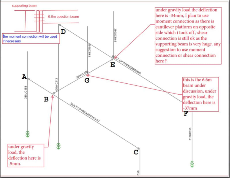
3. I uploaded a sketch for the structure, it's only part of the whole frame. the supporting beam is strong, i can add horizontal support fore the supporting whatever i want, but can't no adjust the depth, i uploaded my sketch how to get additional load due to bean end vertical displacement as well.
 
 https://files.engineering.com/getfile.aspx?folder=ec5ed3e6-ad4b-4ebe-8cbc-5fae87d6e0e5&file=structure_sketches.pdf
I don't follow your 3 sketches at the end.

I'd suggest two shear connections, it makes the beam statically determinate and so the stiffness of the supports is irrelevant (this'll just change the magnitude of the deflections, and not change the loads.)

Not my field, but I don't like your moment connection (just attaching to the web ... looks like a shear connection). For me, a moment connection has good loadpath for the cap loads (the couple that is the beam moment at the end).

"Hoffen wir mal, dass alles gut geht !"
General Paulus, Nov 1942, outside Stalingrad after the launch of Operation Uranus.
 
ArcherC said:
I am designing a 6.6m steel beam with 20mm displacement difference at the ends.

The sketch indicates that dB and dE (where d indicates deflection) = 5mm and 34mm respectively, a difference of 29mm, not 20.

Assuming a pin at B and roller at E, dG = (dB+dE)/2 + PL[sup]2[/sup]/48EI where L=6.6m, not 13.2m.

A moment at point E affects the simple span moment at G, but we don't know the value of that moment from the cantilever platform, so it can't be included at this time. Deflection in Beam B-E due to a moment at E is readily found using moment/area principles.

Capture_szsldy.jpg
 
Hi BAretired,

i used factored deflection in the sketch, the factored deflection 29mm, the unfractured deflection is around 20mm.Sorry for the confusing.

I am trying to figure out is there any addiotnal load due to beam end displacement.

Thank you!
 
If you have shear connections at both ends, then the beam is statically determinate, and the loads are unaffected by the global displacements.

If you cantilever at one end, then figure out the displacement due to weight (I think you say 5mm ... doesn't sound much).
Then for the cantilever figure out the load to deflect the far end the required amount.
Then superimpose these two.
This is not "truth" as the cantilever end is to truly rigid, but it may be so stiff as to be very nearly rigid.

If the far end is a beam, and so the load from the 6.5m beam will cause this end to deflect. This sounds like it'll iterate.

But then I think you're saying that the deflection of the far end is due to the support beam. Then the solution would be ...
1) simple cantilever, which gives a deflection for the far end, d1;
2) a load on the far end on the cantilever, P, gives a deflection of d2;
3) a load P on the support beam gives a deflection of d3; and finally
4) for a reaction of kP (at the far end on the 6.5m beam), the deflection is d1+k*d2 = k*d3 ... k = d1/(d3-d2)

"Hoffen wir mal, dass alles gut geht !"
General Paulus, Nov 1942, outside Stalingrad after the launch of Operation Uranus.
 
ArcherC,

End displacement does not cause any load in Beam B-G-E. It simply moves down as a rigid body, and deflects as a simple span (or in your case as a simple span with unknown moment at E).

If you want to take into account M[sub]E[/sub], we can review that. A moment at E does affect the reactions of Beam B-G-E, and also the deflection of the two supporting beams.
 
Hi BAretired and rb1957,

if they are shear connections on both end, the current design software as far as i know, they can't consider any additional load due to the beam relative displacement. that's the reason why i have concern for the 6.6m beam. For bolted connection, normally bolt hole is 2mm bigger than the bolt, i think 5mm end vertical displacement difference can be ignored, but if the value is greater than this one, from software analysis result, there is no additional load, but in reality it will cause additional force on connection.
I am trying to figure out or looking for any project experience or document can address this issues.

Thank you!
 
ArcherC said:
if they are shear connections on both end, the current design software as far as i know, they can't consider any additional load due to the beam relative displacement. There are not shear connections on both ends. At point B, you have a hinge. At point G, you have an applied moment from the cantilevered platform. The 6.6m beam has a rigid connection to the supporting beam, sufficient to resist the applied moment. The extension to the platform must also resist the same moment.

that's the reason why i have concern for the 6.6m beam. There is no additional load due to relative displacement, so there should be no concern for the 6.6m beam.

For bolted connection, normally bolt hole is 2mm bigger than the bolt, i think 5mm end vertical displacement difference can be ignored, but if the value is greater than this one, from software analysis result, there is no additional load, but in reality it will cause additional force on connection. No! In reality, it will not. Forget about the connection until you have analyzed the structure, then design the connections each side of the supporting beam, one to the 6.6m beam, the other to the extension which supports the platform.

I am trying to figure out or looking for any project experience or document can address this issues. It appears to be a simple structure. I see no problematic issues.
 
Hi BAretired,

I didn't get the point why there is no additional force for shear end connection beam if the beam end has relative vertical displacement.
Let's use 20mm relative vertical displacement as an example. how the connection to accommodate this relative displacement? should cause shear connection deformation, the deformation will result in additional forces?


Thank you!


ArcherC said:
Let's use 20mm relative vertical displacement as an example. how the connection to accommodate this relative displacement? should cause shear connection deformation, the deformation will result in additional forces?

What are you designing here? If it's the frame of a closely engineered air frame with a factor of safety of 1.00000001, then by all means, account for the additional forces. But if it's a relatively typical structure with a factor of safety of 2, 3, or even more....then they won't be enough to worry about.

Countless steel structures have been put up around the world using the assumption that shear connection = pin at ultimate load. Read up on connection design to understand why. They work. Yours probably will, too. Will there be deformation? Yes. Will some of it be plastic? Maybe, even at service loads - certainly will be at your ultimate load. But as long as it isn't completely plastic and hasn't suffered a tensile rupture, you'll be okay.
 
I'm not sure if it has been mentioned here but any normal structural analysis software should take this into account if the structure is modelled as a whole system.

Though like other have already said the magnitude of the effect is likely pretty negligible.
 
Hi ArcherC,

A simple beam with pin/roller support is deemed to have zero moment at each end. That is theoretically correct, provided the supports are true pin and roller. If one support drops 20mm, the end moments remain zero, because a pin can't resist moment.

It is true that we can't build a perfect pin joint (we do our best), but it is standard practice to assume zero moment at each so-called "pin" or "roller" as phamENG has mentioned.

If the small moment resulting from an imperfect pin is to be considered, then it should also be considered for the case where both supports remain fixed in height, because the slope at each end of the beam due to its load is usually greater than 20mm in 6,600mm.
 
Status
Not open for further replies.

Part and Inventory Search

Sponsor