Continue to Site

Eng-Tips is the largest engineering community on the Internet

Intelligent Work Forums for Engineering Professionals

  • Congratulations GregLocock on being selected by the Eng-Tips community for having the most helpful posts in the forums last week. Way to Go!

Beam formulas on elastic foundation 5

Status
Not open for further replies.

mte12

Structural
Mar 1, 2022
141
Has anyone used the formulas in Roark's for beams on elastic foundation, Table 8.5.
Case 2 in Table 8.5, I presume can be used for a beam on ground, without restraints, and evenly loaded with a distributed load.

For some reason, the formulas don't seem to give the same answer as a check in a computer model.

The beam is very stiff, I'm sure the response depends on this, the formulas do have the parameter for inertia, but still getting unexpected results.

Is someone has used and verified, please post a snapshot with sample data to follow.

 
 https://files.engineering.com/getfile.aspx?folder=188ffa06-c3f4-43d2-9b11-4fe74cc678a9&file=Roark’s_213-215.pdf
Replies continue below

Recommended for you

What exactly are you comparing it to?
I assume the formulas neglect shear deflection.
If the beam lifts off the ground, I assume that invalidates the analysis.
Assuming an elastic foundation is different from assuming a semi-infinite elastic medium.
The formulas neglect vertical compressive stresses and associated deflections in the beam web.
 
JStephen, I was comparing to a stick-member with spring supports every 1m. Setting this aside, the Shears and Moments are far too large. The deflections are as expected.
There won't be any uplift as the load is uniform for the entire beam.
Set aside the compressive stresses in the web.
 
If the load is uniform for the entire beam, shears and moments would be zero in the Roark model?
And would be approximately equal to shears and moments in a fixed-end beam of length 1m in your model?
 
Good question, expect shears and moment to be zero. But model results depend on stiffness of beam relative to stiffness of springs. Have gotten parabolic shape as well as a pear-shape.
I don't know enough about limitations of computer models with regard to errors associated with small/large numbers.

Roark does say this: In theory the equations in Table 8.5 are correct for any finite-length beam or for any finite foundation modulus, but for practical purposes they should not be used when βl exceeds a value of 6 because the roundoff errors that are created where two very nearly equal large numbers are subtracted will make the accuracy of the answer questionable.


The total para.

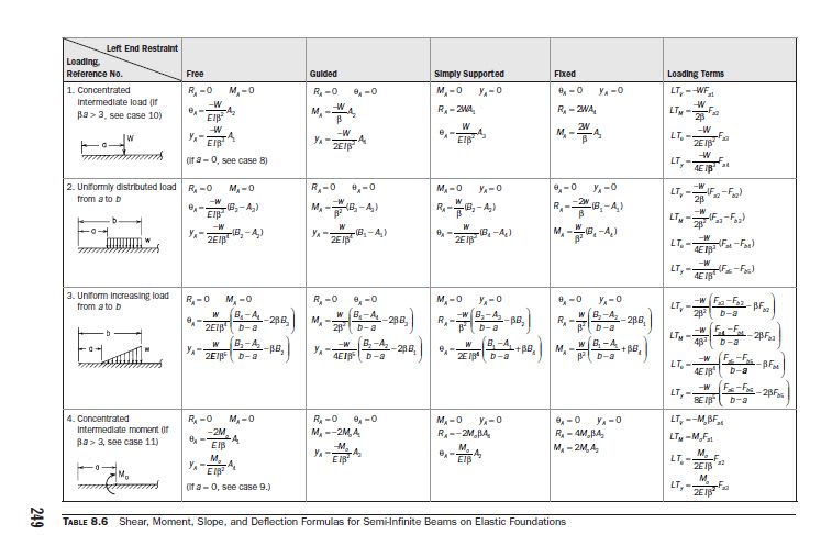
In theory the equations in Table 8.5 are correct for any finite-length beam or for any finite foundation modulus, but for practical purposes they should not be used when βl exceeds a value of 6 because the roundoff errors that are created where two very nearly equal large numbers are subtracted will make the accuracy of the answer questionable. For this reason, Table 8.6 has been provided. Table 8.6 contains formulas for semiinfinite- and infinite-length beams on elastic foundations. These formulas are of a much simpler form since the far end of the beam is assumed to be far enough away so as to have no effect on the response of the left end to the loading. If βl > 6 and the load is nearer the left end, this is the case.

If your case βl > 6, see Table 8.6. Copy and pasted below the same..


ROARK_TABLE_8.6_pu7lxt.jpg


Probably it will be better if you provide more info. regarding your specific case..


If you put garbage in a computer nothing comes out but garbage. But this garbage, having passed through a very expensive machine, is somehow ennobled and none dare criticize it. ( ANONYMOUS )
 
My website ( in its "Downloads" section, contains a program for analysing beams on elastic foundation.[ ] It can handle intermediate rigid or elastic supports, varying foundation modulus, concentrated loadings, partial trapezoidal distributed loadings, and (by an approximate method) lift-off.
 
HTURKAK, it's just a beam on ground, fully loaded along its length, as shown in image.
If the supporting ground is soft enough to deform, expect flexure would be induced. And if ground is infinitely stiff, expect no flexure.
I haven't attached any data because the results are erroneous, and would confuse.
Was hoping someone had created a spreadsheet based on Roark's Table 8.5, Case 2.
Also βl is less than 6.

Denial, thanks for the link posted. I did try the Beam on Elastic foundation but could not run due to limitations on my computer. There are other programs/spreadsheets in there as well which are useful though. Cheers.

JStephen, I think I now understand what you meant by "shear deflection" in first response. Presume this applies if the foundation is assumed to be continuous, with adjacent material affected. The subject is not as straightforward as first thought.

Untitled_qtygkk.png
 
Mte12.[ ] I assume that the "limitations" on your computer are imposed as some sort of security measure by your employers, preventing you from running .EXE programs from an unknown source.[ ] If so, I believe there is nothing I can do to help you get the program running.
 
The curve you have shown above is what the deflection would really look like.
But if you model that assuming elastic support under the beam, and uniform loading on top of the beam, the deflection curve is just a straight line, no shear, no moments. Beyond the end of the beam, there is no load on the ground, thus no deflection in the ground. That same effect will hold regardless of beam stiffness or soil stiffness.
If you approximate the elastic support as springs at discrete points, you introduce bending moments and shears due to those supports.

In "Theory of Plates and Shells", Timoshenko considered both plates on elastic support and plates on semi-infinite solids. But those are two different cases, and give you two different results. The deflection curve you have above is what you get in the latter case, but not the former. The elastic support assumption is used due to reasonable simplicity. If you had that same beam with a point load on it, the performance would probably be more in line with what you're expecting.

The shear deflection in a beam is usually neglected in a hand-analysis, but may be a factor in short beams, shouldn't be an issue in the case shown.
 
Denial, yes I couldn't install due to security measure. But the spreadsheets I can open and will refer to if relevant.

JStephen, I now understand that the textbook formulas differentiate between the two methods.
Will look at the Timoshenko reference next, and take note that shear deflection may be neglected.
 
Looks like an easy problem to solve without any special software. Consider a beam with known stiffness and a finite length supported by springs representing the soil modulus.
 
Mte12.[ ] One possible way to circumvent those "security measures" might be to change the name of the file from BELFAS.EXE to BELFAS.XXX, then copy it onto your computer, then reverse the name change.[ ] (This approach succeeded on my partner's locked-down work computer, but different organisations will be using different security measures.)
 
BAretired & dold, I did start with this assumption and tested model with springs and BOEF spreadsheet, but it is nuanced. Assumption is that soil is discontinuous, each spring reaction is dependent on deflection at that spring, springs don't affect each other. For a case with a beam with uniform load, there will be no shear and moment. Which I don't think is real. The other method is to assume continuity in the foundation but this is more difficult to analyse. I'm attempting to find formulas which give estimations in the ballpark, but no luck so far. Literature suggests that response is complicated and difficult to understand.

Denial, I was able to load the program and got to the point of entering the job name. Tried to input Demo_SimpleBeam but no luck, see attached.

 
 https://files.engineering.com/getfile.aspx?folder=c4b182d9-1b62-4033-90be-35d56311d72f&file=Untitled.png
Mte12.[ ] That message usually means that the program cannot FIND the named file.[ ] This can arise if you do not have both the .EXE and the .DAT files in the same folder.[ ] It can also depend on whether you are running the program by double-clicking upon its name in a Windows Explorer view, or running it in a CMD window.

Please try the latter approach initially.[ ] Place copies of both BELFAS.EXE and Demo_SimpleBeam.DAT in the same folder.[ ] Open a CMD window.[ ] Within that window navigate to the folder containing both the files.[ ] Type BELFAS to set the program running.[ ] Type DEMO_SIMPLEBEAM to tell the program the name of the job.[ ] It should then get on with the job.

If it doesn't, we should resume this conversation via private email.[ ] You will find my email address on my website at
 
Thanks Denial, I did try as suggested and got a little bit further but got some warning messages about output points being too widely spaced for adequate view (reduce length of member ...).
I will contact you at some stage in the next week or so to try and resolve.
Thanks again.
 
The key thing, from my point of view at least, is that you now have the program running.[ ] That message is, as you state, a warning, and it is to be expected with that input data file:[ ] it is suggesting that the modelling could be improved by subdividing some of the member elements.
 
OK thanks for advising Denial.
It will take a while to digest as I'm not used to software such as this. I'm sure it was extremely difficult to compile.
Thanks for your help.
 
You can solve this problem in any FEA software. A two-parameter model (with a "shear deformable layer", which causes coupling of springs) can also be used to model the soil spring in most FEA software.

mte12 said:
Assumption is that soil is discontinuous, each spring reaction is dependent on deflection at that spring, springs don't affect each other. For a case with a beam with uniform load, there will be no shear and moment. Which I don't think is real.
You are correct, but it is very rare to encounter uniform loading onto a beam (footing) or plate (foundation slab) in most structures. The load is rather concentrated point or line load, and this can be modelled using beam/plate on elastic foundation (discrete spring) models. Some literature suggests increasing the spring stiffness linearly from a minimum value in the center to a maximum at the edges of a foundation slab - this supposedly captures "real" (obtained with advanced FEA or semi-infinite medium) response more accurately than when using uniform spring stiffness.

mte12 said:
The other method is to assume continuity in the foundation but this is more difficult to analyse. I'm attempting to find formulas which give estimations in the ballpark, but no luck so far. Literature suggests that response is complicated and difficult to understand.
Semi-infinite elastic medium solutions (or full 3D FEM with soil as solid elements in a large basin) are what you are looking for, but they are not always available in FEM softwares.
 
Status
Not open for further replies.

Part and Inventory Search

Sponsor