Continue to Site

Eng-Tips is the largest engineering community on the Internet

Intelligent Work Forums for Engineering Professionals

  • Congratulations The Obturator on being selected by the Eng-Tips community for having the most helpful posts in the forums last week. Way to Go!

Beam / roof truss Intermediate restraint from steel roof sheeting and purlins

Status
Not open for further replies.

hetgen

Structural
May 3, 2010
219
Hi All,

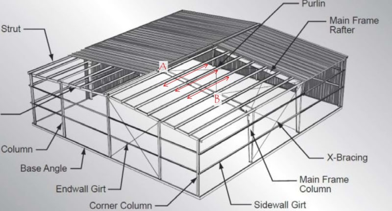
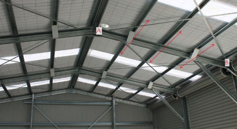
Please see the clips below, is it reasonable to assume that the roof sheeting spaning between points A and B can restrain the purlins thereby providing lateral restraint to the rafter compression flange? If true, are there any guides or empirical rules to check the stiffness and strength of the assembly?

Many thanks.

02_yyzat6.jpg
01_amqnyr.jpg
 
Replies continue below

Recommended for you

Yes and no. The roof sheets and purlins are strong and stiff enough to restrain the TOP flange. But who said that is the compression flange? The bottom flange which also can experience compression along its length likely needs to be restrain as well. In the case of the first picture that is covered by the fly braces.
 
@human909, thanks. I agree, for the bottom flange under compression fly braces are required.

Let's set aside the case where the bottom flange is under compression and only look at the top flange compression case.

[ul]
[li]At points A and B, the compression top chord is restrained by the X-bracing and it is easy to quantify the strength and stiffness of the bracing to compare it with what is required to contain the bucking of the beam.[/li]
[/ul]

[ul]
[li] Between points A and B, can we assume the intermediate purlins as bracing points? if true, how do we quantify the strength and stiffness of the bracing provided?[/li]
[/ul]

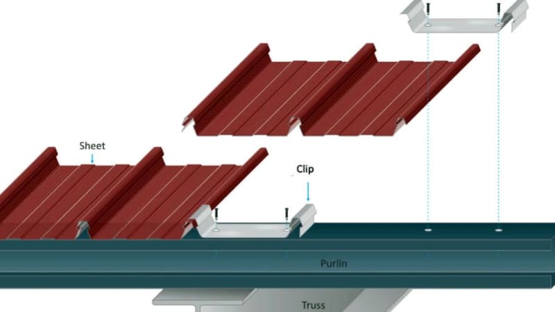
I think the purlins are only restrained by the shear strength/stiffness of the roof sheeting spanning between points A and B, but in most cases, the connection between the purlins and the sheeting is very complex as shown below and not easy to quantify the stiffness.

Perhaps there may be a test done to quantify the shear stiffness of the whole assembly?


03_eaqcn9.jpg
 
Never done calcs on this. In your first post, you asked for empirical rules. The empirical rule is purlins provide lateral restraint to the top flange for normal connections (not much clearance between flange and purlin). The tests are the thousands of buildings where this works. Potential problem is that roof sheeting sometimes ends up in the next suburb in a big storm. Another potential problem is that you'll be drummed out of your job if you worry about the first problem.
 
I have done a lot of looking into this under NZ codes as I used to work with a cold-formed shed supplier and have designed or assessed a few hot-rolled portals in my time.
For us, cold-formed and hot-rolled steel end up having very similar provisions, with the less-developed cold-formed code mostly just pointing us at the effective length provisions of the main steel code
You need to check your own codes first though because obviously things may be different for you, particularly as your portal appears to be cold-rolled

Anyway, I recommend giving this paper a whirl first - it's pretty short and covers off a lot of topics relating to hot-rolled portal frames
This document is a 100% must-read in my opinion, I always recommend it when someone I work with asks about portals

In NZ our effective lengths for bending calculations are based off segments with ends that are "Unrestrained", "Lateral restraint to critical flange only", "Partially restrained cross-section" or "Fully-restrained cross-section"
The code gives a bunch of fancy pictures illustrating various ways to achieve these different conditions

Long story short though, welding a cleat to the top flange of a portal and fixing it to a purlin with 2 bolts is considered to provide both lateral restraint to the attached flange, and partial rotational restraint to the cross-section
So, in NZ, this would give you "Partial" cross-sectional restraint if the compression flange is the bottom flange, or "Full" cross-sectional restraint if the compression flange is the top flange

I am not aware of any guides to check the strength or stiffness of the "assembly" though
I would only ever think about this in the context of assessing the restraint provided to my portal - I would not be trying to create some sort of funky composite structure out of everything
 
Greenalleycat said:
Long story short though, welding a cleat to the top flange of a portal and fixing it to a purlin with 2 bolts is considered to provide both lateral restraint to the attached flange, and partial rotational restraint to the cross-section
So, in NZ, this would give you "Partial" cross-sectional restraint if the compression flange is the bottom flange, or "Full" cross-sectional restraint if the compression flange is the top flange
That is more generous than I would consider a purlin restraint. If you adopt this approach where is the need for fly braces? Also what are your hole tolerances? I'd hope they aren't slotted and oversized holes! I'm an AS user I'd not consider roof purlins as restraining the the bottom flange without fly bracing.

And it would seem that the document you linked agrees with me. The document suggests to avoid a fly brace you need stiffeners and non standard cleats and purlin holing.
 
@human0909, I’m with you on this, but I don’t write the code haha
The commentary requires no more than 2mm oversize holes for this provision to be allowed

A workmate and I spent an hour or two digging thoroughly into this earlier this week, so it is fresh in my mind right now. In the end we decided to put in a dedicated fly brace per rafter, as it seems a tad optimistic to only rely on the purlins

Strictly though, there is a difference with fly braces, as bottoms flange compression with purlins is only partial restraint, whereas fly braces give you full restraint, so there is a potential effective length modifier difference
But that difference is small so it has minimal practical impact IMO

Edit: here is the relevant code commentary

 
hetgen said:
I think the purlins are only restrained by the shear strength/stiffness of the roof sheeting spanning between points A and B, but in most cases, the connection between the purlins and the sheeting is very complex as shown below and not easy to quantify the stiffness.

Perhaps there may be a test done to quantify the shear stiffness of the whole assembly?

You are overthinking things. But if you want to satisfy yourself then you'll have to do the hard yards yourself and make a few assumptions. You'll quickly find that the stiffness and strength of the purlin sheet is MORE than adequate. If you are stuck and unsure on the strength of the clip lock system then start by considerer a self driving screw system. I have no idea how strong the clip lock is but there would have been proprietary testing and there is a reason why there are generally wind limits on where it can be used.

Greenalleycat said:
@human0909, I’m with you on this, but I don’t write the code haha
Well that isn't fun. [tongue]

Greenalleycat said:
The commentary requires no more than 2mm oversize holes for this provision to be allowed

Strictly though, there is a difference with fly braces, as bottoms flange compression with purlins is only partial restraint, whereas fly braces give you full restraint, so there is a potential effective length modifier difference
But that difference is small so it has minimal practical impact IMO
Agreed.

Oh and if you really feel like doing a deep dive on the discussions. THIS thread had plenty of good morsels in amongst the the rest of the discussion:
thread507-459248

THIS blog post by another NZ forum member is also relevant:
(and the rest of the series)

Greenalleycat said:
A workmate and I spent an hour or two digging thoroughly into this earlier this week, so it is fresh in my mind right now. In the end we decided to put in a dedicated fly brace per rafter, as it seems a tad optimistic to only rely on the purlins
Well I must admit I did the same last year for a column and despite my previous comments I called it 'good enough' restraint. This column had purlins on side and cleated beams without a floor on 3 sides. From strict reading this column has no flange restraint on the non purlin side. With no flange restraint the column was failing under LTB with extremely low moments as the effectively length was over 20m. Realistically the purlins an the beams did provide do provide more than sufficient restraint to prevent LTB. But you won't get that answer readily from the code.

(I would use fly braces on portal frame columns which obviously carry significantly moments. This was a braced frame with very minor moments in some columns, so it is a different scenario.)

Greenalleycat said:
Thanks. I think I'll read through all of that. It might be similar to the AS4100 commentary but I don't have that. Besides the NZ code is often a little clearer in minor aspects despite being almost identical in most.
 
Status
Not open for further replies.

Part and Inventory Search

Sponsor