Continue to Site

Eng-Tips is the largest engineering community on the Internet

Intelligent Work Forums for Engineering Professionals

  • Congratulations The Obturator on being selected by the Eng-Tips community for having the most helpful posts in the forums last week. Way to Go!

beam splice - unknown connection detail 3

Status
Not open for further replies.

kingnero

Mechanical
Aug 15, 2009
1,765
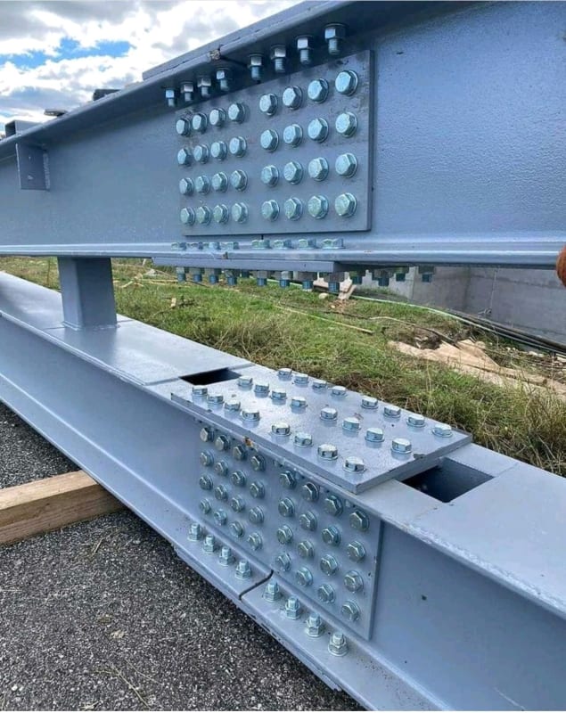
Saw this picture on a social media channel few days ago.
What is the middle bolt row (inbetween both C channels) for?
In europe, there are two kinds of C channels: with parallel and tapered flanges. Anybody cares to guess about those? I don't dare to tell from the pictures, but I don't see tapered washers...

beam_splice_xmjcld.jpg
 
Replies continue below

Recommended for you

The upload process required one more step - pasting the link into the post. No picture.
 
Thx - I edited the post... Had to insert the picture in the body of the post, because it didn't work as an attachment. Tried three times...
 
It is an extra row of bolts presumably to develop maximum flange splice strength possible. They are bolted through a flange/spacer plate welded to the backs of both channels inline with the flanges. This plate also helps complete the built up section.
 
OK, that makes perfect sense to me. So the 4 double C-channel beams look like this:

2021-06-18_12.04.42_bflvwn.jpg
 
1) I agree that the mysterious 3rd bolt row could be for better flange tension development but I favor a different theory. I would bet my britches that there is that welded, flange spacer plate in there though. I think we can see a corner of the weld in the photo. And, obviously, bolting a single piece with no faying surface would be of questionable value.

2) Obviously, guessing at a particular designer's intent in a weird situation is going to be educated speculation.

3) Some reasons that I'm skeptical that this is for flange tension development:

a) That strikes me as an inefficient way to go about that. I think most designers would just add a few more bolts to the flange instead.

b) The connection as shown would introduce a lot of tension force over a short connection distance. I haven't run any numbers but this raises qualitative concerns over shear/tension lag.

c) When you look at how this member is built up, it seems likely to me that it's meant to resist significant lateral load and/or torsional (maybe just LTB). It's rare for someone to go to all this trouble to build a big, kick-ass box and then not use that box for such purposes. And the flange tension development story doesn't speak to this.

4) My Alternate Theory.

I think that this member is designed to resist weak axis bending and/or torsion. As a result, the designer sought to reduce the extent of the permanent gaps between the flanges where the system would revert back to behaving like two crappy channels rather than a proper box. In such a design situation, an intelligent designer is likely to look at those two access gaps either side of the connection and say to themselves "ICK, let's minimize that". I still don't know that the designer truly needed to do what they did here but I certainly understand the impulse to encourage as much composite behavior in the member as possible.

Following this line of thought, the following strategies might have been considered:

1) I want this to be a weak axis moment connection. Maybe a square bolt pattern will be better than just the flanges.

2) If there's real compression or shear in this plate, the third row of bolts over the gap might help prevent local buckling.

3) I want these things to behave as compositely as possible so I'll retain as much perfect shear transfer between the pieces as I can get.

4) I want these things to behave as compositely as possible so I'll minimize the length of my tension connection to reduce the length of any required gaps.
 
Thx to all, and especially Koot for the very elaborate reply...
 
Status
Not open for further replies.

Part and Inventory Search

Sponsor