Eng-Tips is the largest engineering community on the Internet

Intelligent Work Forums for Engineering Professionals

  • Congratulations waross on being selected by the Eng-Tips community for having the most helpful posts in the forums last week. Way to Go!

Beam to beam welded joint 7

Status
Not open for further replies.

GD_P

Structural
Apr 6, 2018
128
IN
Hello forum once again,
It's been great pleasure to be a part of it, for new engineers like me its a great platform to learn the practical design aspects.
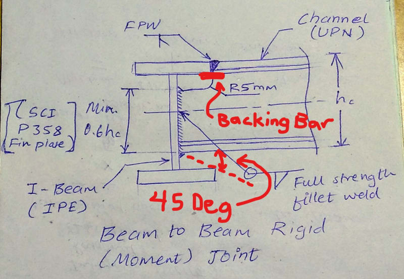
Please share your opinion on below joint details.
I am working on a project involving welded beam to beam joints, please find the attached file for details.
It is a moment type joint, with full penetration weld connecting secondary beam flange to primary beam flange. Corner radius in coping of 5mm referred in EN1090 for EXC2.
Are my consideration regarding the joint details are right.
Do share your opinion.

GD_P
 
 https://files.engineering.com/getfile.aspx?folder=1e42c3ed-0dee-4795-9300-d680b002321b&file=IMG_20180913_202021606~2.jpg
Replies continue below

Recommended for you

Very expensive and why the flange weld? Can you not have a bolted clip angle connection? Unless you have something on the opposite side of the supporting beam, you may have difficulty in achieving a moment resistant connection.

Dik
 
Hello Dik,
Thanks for the reply.
Yes it is expensive but currently we don't have any options, Bec project is already delayed so can't wait for additional hardware & angle clits or fin plates.
Moment connection, I mean to say it (secondary beam) will transfer all moment to supported primary beam.
Can I just transfer that moment only through the web welded and flanges unwelded to supported beam?
One more point, in case of bolted joints either with fin plate or angle cleat, I would have to use coped beam. But as beam flanges are unrestrained (floor used being open mesh grating) there is requirement to prove the notch stability (SCI P358) which is not given in green book for beams with both flange notch. Anyway what you will prefer in such scenario?

What do you think about the joint detail?

Also is it necessary to follow the cutout / corner min requirements of EN 1090-2 cl. 6.7 for attached welded detail? I personally think it is only required in case of coped beams used in bolted connection?


GD_P
 
I think it's awfully 'messy'... you should be able to pick up clip angles this afternoon unless you are in the 'middle of nowhere'... common in even small towns.

I'm not sure of your reference... but cutout/corner requirements are normally used to reduce stress risers...

I'd still look at a clip angle of plate solution.

Dik
 
It is better to wait until design issues such as this have been properly resolved than to rush into hastily considered solutions. Your detail will work but is unusual as it involves costly field welding.

[u said:
GD P[/u]]Moment connection, I mean to say it (secondary beam) will transfer all moment to supported primary beam.
What moment? It would be a torsional moment for the primary beam. Normal practice would be to consider the connection hinged and detail accordingly.

BA
 
The force in the bottom flange of your channel has to go somewhere - is the web of your primary beam capable of transferring this force? Also, depending on the proportions of your beams, you may not have access to place the fillet weld on the underside of the channel. Ideally you would maintain a 45deg line of sight to your weld so the electrode can make a proper angle for the weld.

To get the full pen weld on the top flange, you'll likely either need a backing back on the underside of the flange or you'll need to gouge to sound metal on the underside...either way, I believe your beam web will have to be coped further back than you have shown.

aa_r0r3hp.jpg
 
As dik and BAretired indicated, making the connection rigid does little good, as the supporting beam is not much good in torsion.
 
Thank you all for your valuable opinions.

Yes Dik, as far as extraa material is concerned I am in the middle of nowhere, unfortunately.
You are right BAretired, But it is a part of shop-welded structure, otherwise there would have been a problem.
Also the primary beam is also checked for the torsion resulting from secondary beam (although it is small)

CANPRO, thanks for your insights about the datail.
As far as the bottom flange to web joint is concerned, I think of the fin plate welded to beam connection, although it is modeled as bolted/hinge connection, it can also transfer enough moment through only the thickness of the plate connected to web.
Whereas in this case both bottom flange & beam web are available to disperse the force into the web of the supporting beam.
But as of now I dont have justification in terms of numbers.
Also is it necessary to weld the bottom flange, since it only going to bear/rest against the supporting web. But it only need to be sealed around its periphery to avoid any corrosive media to enter on its bearing surface.
For top flange weld, we were planning to backgouge them, with current detail probably it will require tip grinder near the coped web.

In case of bolted joints involving fin plate & coped beam with flanges, do you justify the notch stability (SCI P358) which is not given in green book for beams with both flange notch. Or you just use the criteria of short fin to notch and close this matter.


GD_P
 
@GD_P
Some points below:

- Do you really need FPBW for top flange which is tapered of UPN because there is no way that supporting beam IPE can resist that much torsion induced by the full strength of UPN.

Since you mentioned this is a grating floor with a cantilever on one side. It is assumed that no heavy duty on this floor, so a couple of simpler connections can be offered such as a welded toe plate in between IPE & UPN or a projected fin plate welded on the back of UPN, etc…

- Regarding cut-out radius as per EN 1090, it is certainly required for EXC2 in both welded or bolted connections since the reason behind it is about the stress concentration.

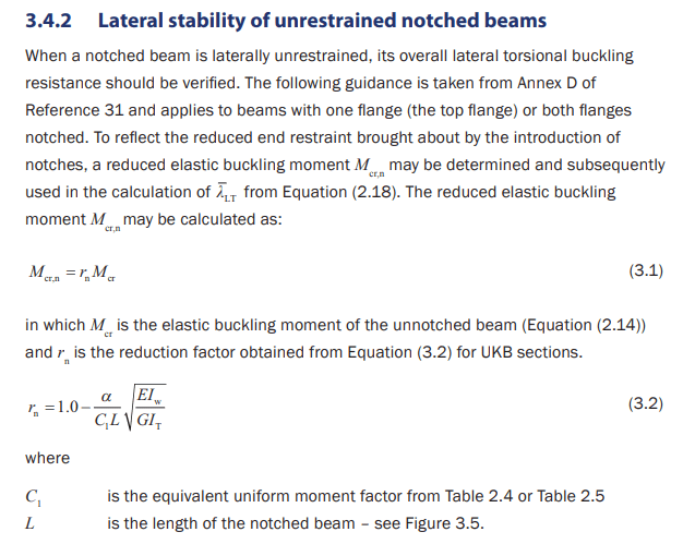
- Regarding the stability of double notched unrestrained beams, SCI P360 may be useful for you:

3.4.2_mcgdaj.png


For a better understanding of stability in EC; ECCS Pub. 119: Rules for Member Stability in EN 1993-1-1 is a worthy starter.

Regards,
 
I tend to agree you are better off using a nominally pinned detail, unless of course you require to transfer the moment/torsion for purposes of equilibrium. For exmaple if you were cantilevering the beam off the primary beam (a bad detail, but provided to demonstrate the requirement for equilibrium).

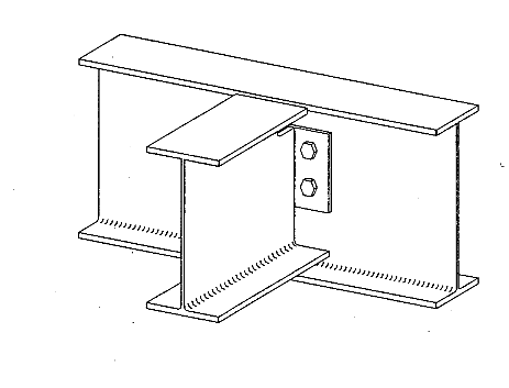
Unsure if you have access to flat plate and bolts, if so why not use a flexible end plate detail. Alternatively, make some clips out of a bit of beam section, cutting off one flange, or weld two plates together to form a clip angle, etc. Use you imagination, steel is good for that :).
Untitled_dw7mgy.png
 
Why not weld only the web to the supporting beam? Less welding, far easier to construct, no force transfer from flanges. Just size the weld to develop the yield strength of the web it is attached to.
 
@Istructeuk,
You were spot-on.
Partial penetration butt weld with depth equal of min thickness of UPN will also suffice.
Beams are not cantilever type, but they are supported on both sides with moment connection. There are many such beams on floor which support grating as well as some pumps & accessories. Hence i think, above details with PPW welds on both flanges will suffice.
Thanks for the reference documents. I will go through it.

@Agent666
Thanks for your alternative solution. Bolted connection is not feasible at this situation, and Weleded can not be used as shear only connection.

@canwesteng
If the connection is welded essentially it will transfer moment to connected beam, so how can we treat it as shear connectins only


GD_P
 
GD_P, depending on the rotation that occurs at the end of the supported beam, the welded detail and supported beam will pretty much be simply supported. The beam you are connecting to is torsionally flexible, so will rotate to a state to maintain equilibrium. The torsion being transmitted to the supporting beam is equal to the negative moment at the end of the supported beam.

A torsion will develop in the supporting beam (how small/large depends on relative stiffnesses, loads and resulting deformations/twists), so if welding it is the only option then its a matter of designing the supporting beam for the moment/shear/torsion present using the relevant combined actions checks in your local codes. If the torsion is small then with some judgement it might be able to be ignored (see below).

Consider alternatively for a minute this scenario, with a bolted web/fin plate or clip angles, there is also an eccentricity from the supporting beams web to the line of bolts through the supported beams web. This creates a similar torsion to that noted in your welded scenario in the supporting beam, the end of the beam delivers the nominally simply supported shear (V*) at some eccentricity (e) to the web creating a torsion (=V* x e) (that is typically ignored in design I'd say without giving it a second thought). The twist in this system of the supporting beam is probably higher than your welded scenario for the same load as the vertical row of bolts uses up the tolerance in the bolt holes to go into bolt bearing on the web plate to transfer the shear and moment at the location of the row of bolts.

Your scenario by comparison essentially delivers the shear to the face of the web (A much smaller eccentricity), and the twist of the supporting beam is constrained to the rotation at the end of the supported beam. I would hazard a guess that the torsion is therefore lower than the equivalent nominally pinned bolted detail. As noted the torsion in the bolted detail is often neglected in design checks. As an exercise, if you took your shear and said it was a bolted connection at 50mm eccentricity, is the resulting moment at the center of the supporting beam from this eccentricity of the shear less than the moment seen at the ends of your model with all fixed connections.

If it is less than I'd be fairly happy ignoring it because its done inadvertently all the time by designers, then it just comes down to making sure the connection is detailed appropriately in the terms others have raised regarding weld access and the like. If the torsion delivered to the supporting beam is higher in your fixed model than the equivalent pinned bolted detail, then exercise some judgement as to whether you need to specifically check the supporting beam for combined actions including the effects of torsion.
 
Hello Agent666,

You have justified : "Use you imagination, steel is good for that :)."

Yes the moment depends on the rotational stiffness and it is less than the equivalent nominally pinned connections for most of the beam.

I am very glad & thank you very much for the explanation.


GD_P
 
Status
Not open for further replies.

Part and Inventory Search

Sponsor

Back
Top