Continue to Site

Eng-Tips is the largest engineering community on the Internet

Intelligent Work Forums for Engineering Professionals

  • Congratulations IDS on being selected by the Eng-Tips community for having the most helpful posts in the forums last week. Way to Go!

Bednar's Leg Design Method

Status
Not open for further replies.

JStephen

Mechanical
Aug 25, 2004
8,626
I've wrestled with leg designs through the years, and am just now looking through some of the details of Bednar's method.
Reference: Pressure Vessel Design Handbook, 2nd Edition.
The issue I find is than an unbraced leg subject to lateral loads has to have applied moments somewhere. The leg could be assume "fixed" to the vessel and pinned at the ground, or "fixed" to the ground and pinned at the vessel or fixed at both ends, etc. but can't be pinned at both ends. It seems Bednar assumes 3/4 fixed to the ground, 1/4 fixed to the vessel- which he handles by placing the lateral load at 3/4 of the actual height.
So, at the bottom of Page 147, he gives an equation for moment in the leg that includes Fx3/4L term that represents this assumption.
On Page 151, for the moment in the weld to the shell, he includes an FL/4 term that also fits this assumption.
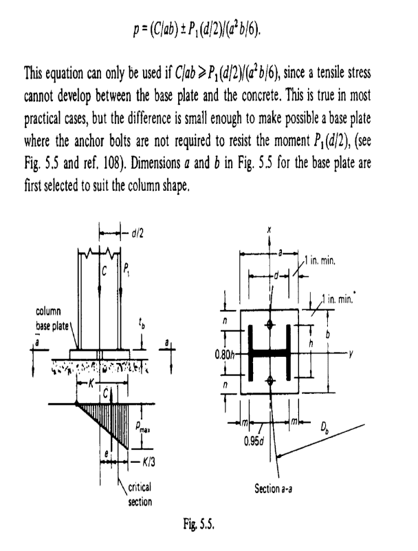
The problem is, in the design of the base plate, Page 149, he takes the moment on the bottom of the plate as only being due to the eccentricity- no Fx3/4L in that term.
So am I missing something here, or did Bednar blow it?
If you try to include that 3/4FL moment on the base plate bearing, then you just can't make the base plates big enough per his design procedure.
Yet, I can't see any reason to exclude that moment, either.
Any ideas?
 
Replies continue below

Recommended for you

Please see that P1 includes the moment Ma = PH in figure 5.4 and then it is applied in the formula on page 149.
I don't see anything strange.
More clear is Pressure Vessel Design 4th ed., by D. Moss.

I hope it help you

Regards
 
Yes, the overall moment as shown on in Fig. 5.4 is correct.
It is the moment in an individual leg, that is omitted in evaluating the base, that is the issue.
Note the moment contribution from 3/4FL in the equation for fb on Page 147- which is omitted in Fig. 5.5.
 
F(3L/4) is only for the column (shape), not for base plate
P1 is used for base plate calculations. Base plate not depends of L

Buckling of legs is not included by Bednar. Buckling must be checked

Regards
 
That's exactly my point- his moment immediately above the base plate includes F(3L/4), while his moment immediately below the base plate does not- but should- where did that moment go?
And note this is 3/4 of the moment that prevents the legs from folding over at the base- it's not negligible or trivial.
 

Mr . JStephen (Mechanical)(OP) I looked to the same page and copied and pasted below ;
P1_correction_xqwmbb.png
.

You are wright ..moreover, the term (C ) is equal to P1 for the leeward column.

the bearing stress formula for the leeward column base shall be ;

p= C1/(a*b) +,- ( M1/ W ) Where, W= section modulus for the base, W=(a**2)*b/6

C1= (W0/N)+ 4Ma /(N*D)

M1= F1*L*3/4

F1= P*I1/( Σ I)

the bearing stress formula for the windward column base will be ;

p= C2/(a*b)+,- ( M2/ W )

C2= (W0/N) - 4Ma /(N*D) and M2 = F 2 *L*3/4 In case of equal sections (which is common), F1= F2
 
I would agree, it doesn't seem correct, if C is the compressive reaction then the diagram should be corrected. The eccentric loading caused by P1 is more relevant to the buckling assessment. The moment generated by P1 is opposing the moment at the base plate, caused by the lateral load F, so I would exclude it and design for the base plate moment M (which should be higher). If you are treating the base plate as a moment connection then it has to be capable of transmitting the equivalent loads to the footing, typically this would required anchor bolts outside the flanges, not covered by this method which is pin connected. So the inequality that would need to be satisfied should be based on the leg moment M at the base plate. You could have some uplift provided the bolt doesn't see prying loads, otherwise design as a moment connection. I also see an issue for bearing loads on saddle supports in Moss (Bednar isn't any better), the maximum bending component is added to the vertical load and averaged over the full base plate area to get the bearing pressure, but the bearing pressure over part of the base plate will be higher and would require a thicker base plate if calculated accordingly.

The amendment by HTURKAK is conservative, since the bearing pressure is calculated based on the peak moment. You could get suitable result by averaging over the area that is actually in compression from the moment or using a 1/3 type distribution (similar to the figure posted above).
 
Correct procedure (the best) for base plate is AISC Manual.

Regards
 
The bigger issue to me is that the method can only be used if base plate bearing pressure calculates positive all across per his comment, but if you apply the design leg moment, that is almost never the case.
 
Consider that vessel design with legs support is good when wind /seismic is low. Otherwise a skirt is required.

Regards
 
Essentially, you would only ever used the pinned base plate with braced legs. Without bracing always use a moment connection, but this would only be applicable for relatively moderate loads or the design will be far too inefficient. It is a bad example to include and should not be used as a design guide.
 
Status
Not open for further replies.

Part and Inventory Search

Sponsor