Eng-Tips is the largest engineering community on the Internet

Intelligent Work Forums for Engineering Professionals

Belleville Top Ring? 4

Status
Not open for further replies.

RodRico

Automotive
Apr 25, 2016
508
0
0
US
The discussion in another thread regarding piston seals got me thinking... Why not use a single piece "ring" attached to the top of the piston that acts somewhat like a Belleville disk spring? Like a Dykes ring (my baseline), it would be pressure backed such that combustion pressure increases seal pressure. Unlike a Dykes ring, however, I would have no gap and I think it would be easier to control in terms of flutter and twisting.

The picture below shows the Dykes and Belleville top ring approaches side by side. I will obviously have to tune the critical thickness, curves, support, and attachment method, but the picture should convey the general idea. What does everyone think? Am I nuts?

Belleville_Ring_wojrf8.jpg
 
Replies continue below

Recommended for you

I would worry about the seal wanting to pull away from the flat piston face as it retracts (moves downward in your picture) when combustion pressure is not present (assuming 4 stroke operation). Even if it springs back in place when motion is reversed you could get a build up underneath the edge over time.

I have no experience whatsoever in engine design so feel free to tell me I don't know what I'm talking about.
 
Your design has no initial pressure wall pressure and no visible path for cylinder pressure to for the ring outward. Also, there is no gap for thermal expansion and taper compensation.

To get a rectangular cross section ring to dish like your proposed belleville, manufacturers add a bevel to an I.D. edge. Beveling the upper I.D. edge will cause the outer edge to turn towards the top of the piston slightly. The causes the bottom edge of the ring to contact the bore wearing that edge more quickly. A groove on the bootom outside edge will also cause the ring to "twist" in a similar fashion.

A bevel on the bottom I.D. edge reverses the ring "twist" and normally requires a larger face taper to keep the bottom edge of the ring working as a scraper.

 
Pass #2 responding to comments.

By increasing the angle of the ring, I've converted what I was calling a Belleville Ring into an Obturator Ring such as thise used in WWI era radial rotary engines. In the original application, these type rings were used to compensate for bore distortion and were made of soft material that wore quickly. In this application, bore distortion will be imperceptible and and the ring will be made of steel.

Relative to the Belleville concept, the Obturator Ring has an increased contact angle to prevent binding, and the longer cone wall allows for greater displacement at lower tension. The outside diameter of the ring would be very slightly larger than the bore at max taper width and would compress both as the bore tapers and the ring expands under thermal load. The tension in this ring would be on the outside radius where it transitions upward from horizontal and will be related to the thickness of the ring. I will calculate bend radius and ring thickness then run it through FEA at temperature if and when this concept passes initial sanity check.

For context, my prototype bore/stroke is only 1.060"/0.375" and all components (piston, ring, and cylinder wall) are steel. Under these conditions, there's not a lot of thermal expansion going on (I was planning 0.003" end gap). Note my pistons have no wrist pins and are not subjected to lateral loads, so my bore is as perfectly round as possible. Also note my engine is an opposed piston two-stroke with no valves, and that's why the piston faces are flat. I selected the Dykes ring as my baseline because my engine has very high combustion pressure (220 bar) due to HCCI and low exhaust pressure due to over-expansion. This wide range of pressure suggests gas loading of an otherwise low tension ring. Of course a rectangular ring can also be gas loaded, but the Dykes ring facilitates two-stroke timing and port flow by closing ports at the top of the piston rather than further down the crown. Even with only a 0.003" gap, the very high combustion pressure of my engine would result in significant blow-by, so I first tried designing a zero-gap Dykes. I found it clumsy, however, and the [link bridgestonemotorcycle.com/documents/l-ring_effect6.pdf]Dykes has other challenges[/url], so I started exploring these alternatives.

I know this exploration seems kind of wild and really appreciate your patience and comments!

Obturator_Ring_yf9hlg.jpg
 
Not much room for ports with a 3/8" stroke.

What do you hope to gain from the second ring in a two stroke? Oil control?

Have you looked at ablative coatings for the piston to minimize clearances? I like the sound of ablative obturator.
 
Normal "gapless" rings that I am aware of, still have a gap, but it is a stepped overlapping design so that there is not a direct path through. They're still free to expand and contract to allow for differences in thermal expansion.

Hydraulic cylinders and the like which have actual "gapless" seals - usually U-cup in profile or something of that sort and made of rubber/neoprene/teflon/whatever - aren't trying to seal combustion temperature inside and they're not trying to accommodate mean surface speeds of 20 - 25 m/s.
 
Gruntguru, compliance should increase with height and reduced thickness. I suppose I'll go ahead and do some quick FEA to better understand and convey its behavior under stress.

EHudson, Yes, the 2nd ring is for oil control. I wasn't clear regarding stroke. The engine is opposed piston and the distance between the bottom of the intake port and the top of the exhaust port (both intake and exhaust just closed) is 3/8". The distance from the top of the intake port to the bottom of the exhaust port (both intake and exhaust wide open) is 0.482" The two pistons do not share the same stroke distance or timing. Ports are 0.052 x 0.170 and there are 8 each for intake and exhaust. I calculated mass flow using the combined area, a 0.6 Cd, and a 1/8 bar pressure differential for scavenge/intake (exhaust differential can be higher of course). Note the physical displacement of an individual cylinder in my prototype is only about 5.6 cc, so there's very little mass being moved.

BrianPeterson, I'm familiar with gapless rings (though certainly not an expert); you're describing the two part Total Seal solution. Others use a "zero-gap" approach with overlapping segments in a one-part ring. I believe the cone in my concept ring will expand and contract under pressure, and will do some quick FEA to confirm. My peak piston speed is 12 m/s, by the way. I have high piston acceleration, but mass is low, and the time period of acceleration is too short to accumulate into large piston speeds.

I'm going to do some FEA work today and will post results when complete. My greatest worry is that the cone will "wrinkle" under compression.

 
I got distracted by questions from my patent attorney and had some trouble getting Solidworks to transfer thermal results into stress analysis, but I finally got it done.

All parts are steel, and the piston and rings are installed in a cylinder with its walls held at 127C.

The thermal plot shows the piston crown is at just under 400C, well above the 165C value shown in Figure 11b of this paper (I used a high value because I wasn't sure how well the rings would cool the piston). The portion of the top and bottom ring where they contact the cylinder wall is 187C, a 60C rise. The top ring has a very small contact patch with the piston, so it contributes little to piston cooling. The bottom ring has a larger contact patch and contributes significantly to piston cooling. It does, however, cool the area below the ring much more than the rest of the piston body, and this creates thermal stress in that region of the piston.

The stress plot unsurprisingly shows a lot of stress wherever there's a significant change in temperature. Both rings show similar stress where they contact the wall and piston body.

The displacement plot shows the expected radial dispersion of displacement throughout the piston. The top ring is displaced by about 0.0015 per side as would be expected from the normal rule of thumb for ring gaps (0.003" per inch of bore). The lower ring is displaced much less due to its lower temperature and its use of a ring gap.

On the next pass, I will increase the contact area between the top ring/piston body and 3200 PSI (220 bar) pressure on the crown and top ring.

Thermal_mqwrjm.png
 
enginerus, is there some inherent reliability flaw you see in this approach? If so, please share.

Note that this ring is for the prototype. Production engines (if any) will presumably be designed by a more experienced group of engine designers funded by investors. Production designers will never even get their hands on my engine unless prototype performance measured by a third party tester is promising, however, and this approach eliminates the blow-by variable in the prototype. If I prototype with a ring that differs from a production ring, then my test results may be tarnished a bit, but there are *plenty* of other areas of optimization the professionals will complete using their gazillion dollar tool sets, so I'm not too worried.
 
Since you are fiddling with your FEA, how about looking at the contact pressure/force between the top ring and the cylinder under the following conditions:
- Same as what you did above - presumably somewhere near normal operation
- Cylinder, piston, and ring all at 0 degrees C - "cold start" - Does the piston ring remain in contact? Does its contact force increase dramatically?
- Cylinder, piston, and ring all at 120 degrees C - "heat soaked". Same questions.

I'm still concerned that your gapless design has inadequate "give" in the diameter direction. A normal piston ring with a gap - including the so-called "gapless" designs that use an overlapping gap - experiences very little difference in contact pressure regardless of (reasonable) operating temperature or differences thereof ... until the gap closes up (assembly/tolerance error), or it gets loaded up with carbon deposits and seizes, and then you scuff the cylinder and break things.

U-cup seals in air cylinders and the like don't have that issue because the seal is so flexible that it accommodates the thermal expansion without issue.
 
BrianPeterson, I'll tackle your suggestions Monday (I have a family event tomorrow). In the meantime, I can give some quick answers.

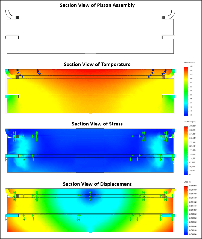
My thermal analysis was steady state, so I didn't worry about initial internal temps of the parts. It wouldn't matter if I were only doing thermal, but I'm doing thermal induced stress, so the initial temperature of the components matters. According to this article, since I didn't set the initial temperature on the parts, Solidworks likely defaulted them to 0 Kelvin (!). The stresses and displacements I plotted may thus have been those associated with a temperature rise from 0 Kelvin (-273C) to just under 400C ! I'll obviously need to check that Monday. [smile]

The operating temperature of the engine should be limited on both the low and high end by the oil. The 127C wall temp I selected relates to max oil temp before it no longer lubricates the cylinder walls effectively. The minimum operating temp is determined by the point at which the oil and fuel gel (this article suggests a block heater below 20F, so that's probably a number for min operating temperature). Process wise, I believe the piston and rings would be chilled then installed into a heated block to effect a moderate interference fit.

I get that folks are concerned about expansion. Let me see if I can explain why I think this is worth exploring. My ring is very small (1" diameter, 3.14" circumference) and will expand one fourth as much as a standard ring (nominally 4" diameter, 12.6" circumference). The rule of thumb for ring gaps is 0.003" per inch of bore, so the standard ring's circumference expands about .0120" while mine expands 0.003". Now imagine trying to press fit the 4" rod into a 3.988" hole (0.12" interference) and the 1" rod into a 0.997" hole (.003" interference). The attempt to press fit the 4" rod will fail unless you bore out its center and cut a notch in it that allows compression of its circumference. The 1" solid rod will, however, press fit readily, and the pressure required to do so can be reduced by boring out its center to make a thin walled pipe, no notch required. From this, it's clear my ring will certainly be unsuitable for a large engine. That's OK. All I'm trying to do is eliminate the risk of blow-by and ring flutter in my small prototype. My prototype already suffers from low volume/surface area (like any small engine), so I may as well exploit its small size to get some gains in the area of ring performance. I don't doubt it will "work," but I do think it may be a challenge to minimize wall pressure when unloaded with gas pressure while still holding up under 220 bar combustion pressure.

Thanks for your continued input! I'll get back to you when I resume the simulations.
 
This looks like an unnecessary diversion to your development of an engine that is already radical in so many ways.

The piston ring needs to be able to expand and contract significantly as the temperature difference between ring and cylinder varies significantly in operation. The fit of a "continuous" ring in the cylinder will vary so much that you will have either excessive clearance, excessive interference and probably both at different condition. If you make the ring thin enough to reduce the contact pressure to normal levels it will buckle.

je suis charlie
 

I'm guessing that the first image shows a disk that secures the ring to the piston and also is part of the combustion chamber.
Maybe the disk is secured with a bunch of bolts, or ???
I'm guessing that the interface between disk and piston will not conduct heat very well, compared to a one piece piston.
I'm also guessing the thermal profile in the second from the top image represents perfect thermal conductivity between disk and piston.

How'd I do?

Dan T
 
Tmoose, yes, the interface between the piston crown and body is bonded in Solidworks (per Solidworks, "bonded" is essentially "welded"). I will either change that to "insulated" with an appropriate heat transfer coefficient or explore other means of fitting the crown into the body (such as press fit). Caterpillar used two piece pistons, and Mahle offered them as well for a while, so I'm sure the thermal challenges are solvable. Right now, I'm simply exploring if this ring concept makes any sense whatsoever in terms of thermal expansion and wall pressure.
 
If the ring retains "Belleville" functionality, is there no concern for leakage during the intake stroke?
Or would this be considered a "benefit"- built in positive crankcase ventilation...
 
Jack Gifford, it's a dry-sump two-stroke with a separate piston dedicated to providing the scavenge/intake charge, and the underside of all pistons is vented to atmospheric.
 
Status
Not open for further replies.
Back
Top