Continue to Site

Eng-Tips is the largest engineering community on the Internet

Intelligent Work Forums for Engineering Professionals

  • Congratulations IDS on being selected by the Eng-Tips community for having the most helpful posts in the forums last week. Way to Go!

Bending Capacity of Plate 1

Status
Not open for further replies.

Vrpps EIT

Structural
Aug 21, 2018
58
Hi All,

Attached a detail, where a steel saddle is welded to a plate which in turn is fastened to Concrete wall with anchors. As the saddle is welded to plate it creates a moment there also the plate at the top (1/3) is left free as the concrete wall is below the top height of the plate.
1. In this scenario should the plate be checked for its bending capacity as it experiences a tensile pull at the top duet to the moment, if so how to calculate the resisting moment capacity there?
2. Irrespective of it should it be restrained at the top free part by connecting it back to the foundation wall with the gusset plate?
3. I hope the bolts here are only for shear transfer? or does it have to be checked for its tensile and pull out capacity caused by the moment at the top

Thank you guys!
 
 https://files.engineering.com/getfile.aspx?folder=1e16b1fe-3e87-46cf-b5dd-327e6bf41887&file=Scan001_(3).jpg
Replies continue below

Recommended for you

1) I like your idea of putting a gusset underneath the seat in which case I see no need for checking the plate above, or the LVL bolts, for bending/moment. Otherwise, I do think that you need to check the vertical plate for bending. [phi x Fy x Zx]

2) In conventional situations, I would avoid trying to transfer moment into the LVL via the bolts. The constructability detailing in these situations, which allows for tolerance in LVL bolt hole locations, usually results in horizontally slotted bolt holes in the steel side plates which would neuter moment transfer.

3) Give some consideration to the moment delivered to the concrete bolted connection as well of course.
 
Thank you KootK, in the concrete bolted connection, to convert the moment into a pull-out force should the moment be divided by the distance between two bolts (arm length)?
 
Vrapps EIT:
I would not weld the two saddle side pls. to the .5” thk. (embedded?) end pl. for a couple inches above and below the top of the conc. wall. Basically, I would like that .5” end pl. to be able to bend in that region, without being stiffened by the side pls. so that it can more readily conform to the rotation of the end of the LVL as it rotates due to the LVL deflection. Still, the side pls. are important to provide some lateral rotational resistance for the LVL at its bearing end. Take the reaction load from the LVL out through the bot. pl. of the saddle, and two bolts would probably be sufficient.

Alternatively, make a saddle out of two side pls., an end pl. and a bot. pl., all one fabed. unit, with a couple through bolts. Then, weld an angle on the outside (end) of the end pl. with its horiz. leg resting on the top of the conc. wall, with a couple A.B’s. into the top of the wall. This detail can rotate with the LVL as it deflects, without inducing any significant moment at the end of the LVL and its bolts.
 
I don't like gusset plates... costly... and you might want to reconsider the number of bolts. LVLs are generally dimensionally stable, but with timber, I don't like to use fasteners that will resist shrinkage and cause splitting.

What are your loads like? Do you need 1/2" plate?

Rather than bolts, can you use headed studs?

Dik
 
Vrapps, to resolve the moment, you can consider the moment couple across your concrete bolt/anchor/stud spacing. This will be conservative, but is sometimes still gives reasonable results (depending on loading and geometry, type of anchor, etc).

Alternatively, you can take a more refined approach that considers the bottom of the steel plate bearing laterally on the concrete, which gives you a longer moment arm (and potentially all four bolts contributing in tension, although the top two will take more). Similar to a reinforced concrete beam compression in bending, with a compression block and 4 "reinforcing bars) in a cross section.

----
just call me Lo.
 
@Vrapps EIT: It would seem that I disagree with all of my colleagues here in some measure. It looks as though you will have to be the arbiter of righteousness for your connection.

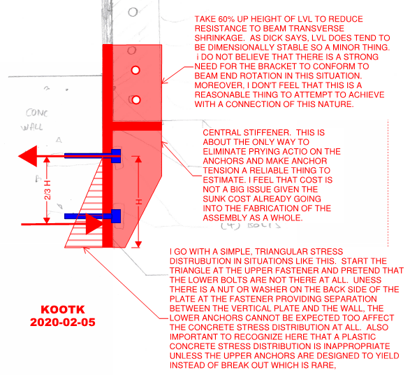
c01_qpzoph.png
 
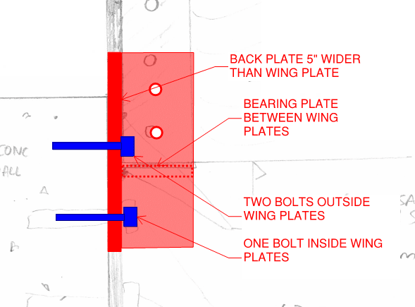
Another option if there's space and you're looking for something a little more compact and less fancy.

c02_vf35lo.png
 
Thank you all guys, it gave good insight. Appreciate your time!
 
Kootk, I like your last detail (the less fancy one) it is very ideal!
 
To tease this out a little, I'm not so sure that the stress distribution you (KootK) show is inherently superior to a distribution concentrated at the bottom of the plate. (Except maybe in efficiency of design effort). At the moment, I'd put this in the 'reasonable engineers may differ' category, but I'm happy to be convinced otherwise.

My thinking is such: Due to any number of causes, the two surfaces are unlikely to be in full contact while the load is applied. These anchors aren't being pre-tensioned to any substantial measure. Some potential sources of gaps:
[ul]
[li]initial imperfections in the surfaces[/li]
[li]Take-up in the anchor/nut[/li]
[li]elastic stretch in the anchor[/li]
[/ul]

This gap means that as the plate pivots about the top bolt, the bottom edge bears first. At this point, the moment arm is maximum, so the anchor tension is below the final design value.

As the load increases, concrete begins to strain (or the plate flexes), and additional plate area is mobilized in bearing. The concrete bearing block grows and migrates upward until equilibrium. In a working installation, this happens before the moment arm gets so short as to overload and pop the anchor.

So it seems to me that a stress block concentrated near the bottom edge (or at least a "masonry-style" triangular block that doesn't necessarily reach the top bolt) is reasonable.

----
just call me Lo.
 
Lomarandil said:
To tease this out a little, I'm not so sure that the stress distribution you (KootK) show is inherently superior to a distribution concentrated at the bottom of the plate. (Except maybe in efficiency of design effort).

"Superior" is a bit strong for my liking but the distribution that I proposed does have three advantages:

1) it's computational expediency as you mentioned.

2) it's likely to be conservative in a situation where the accurate assessment of the stress distribution is problematic.

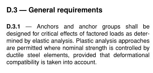
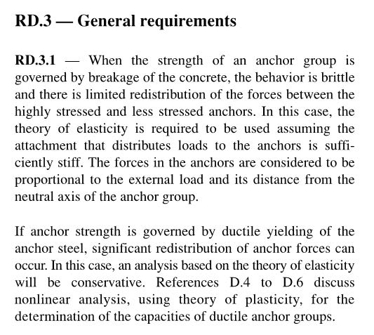
3) it does not suggest a plastic stress distribution predicated upon the ability of the anchors to yield plastically before initiating concrete breakout.

If my method produces results that I feel are impractical, I will consider more agressive stress distributions

Lomarandil said:
This gap means that as the plate pivots about the top bolt, the bottom edge bears first.

It seems to me that all of your gap sources could just as easily produce a first contact point anywhere up the height of the plate and, therefore, the system might not pivot about the top bolt and may well exacerbate potential prying issues. This is a bit of a slippery slope rationally.

My expectation is that the substrate would be flat enough that:

4) Smallish surface imperfections would crush and redistribute stress.

5) Plate deformations would help to redistribute stress.

It's tough to design a thing without relying upon the quality of that thing to an extent. If the wall face looks like the Rockies viewed from 10,000 ft, them I'd want some grout between the plate and the wall.

Lomarandil said:
...or at least a "masonry-style" triangular block that doesn't necessarily reach the top bolt...

Sure. But then any stress distribution with a neutral axis lower than the top bolts implies meaningful strain in the upper anchors which have a very short stretch length and, usually, a brittle governing failure mode. The use of the rectangular and masonry triangular stress blocks is common and shows up in the literature. It's simply not my first choice for lightly loaded things for the reasons that I've mentioned.
 
Lomarandil said:
To tease this out a little...

I guess we're done with this? I was hoping for another salvo or two on steel to concrete connection theory. Although it mostly does mostly just come down to the statement below.

Lomarandil said:
I'd put this in the 'reasonable engineers may differ' category
 
Fear not, salvos (or retractions) still pending! I was just out of the office for a little while.

----
just call me Lo.
 
I've always used the rectangular stress block as Lo indicated... if it works for concrete... steel is much stiffer. It's easier to calculate and yields a slightly stiffer plate.

Dik
 
dik said:
I've always used the rectangular stress block as Lo indicated...

As I mentioned above, that method is ubiquitous in the literature. And I've got several "big firm" design guides that show it that way. It was one document in particular that turned me on to what I believe is the error in that approach however. I wish I could find that now. Pretty sure it was PCA or ACI.

dik said:
if it works for concrete...

And therein lies the rub. In at least one important way, an anchorage system is different from conventional reinforced concrete:

1) Developing the rectangular stress block approximation in concrete is predicated on being able to strain the concrete to 0.003.

2) Being able to strain the concrete to 0.003 is predicated on being able to strain the anchor/reinforcement to 0.002.

3) Being able to strain the anchor/reinforcement to 0.002 is predicated on the anchor not tearing from the concrete prior to yielding.

It is #3 that is often difficult to achieve and thus, I feel, invalidates the use of the rectangular stress block in many scenarios.

 
Agreed, Koot... but none of these has any effect on the shape of the stress block. I'm happy with rectangular and it's easier and faster than triangular or paraboidal... I'm comfortable, and sleep at night.

Dik
 
dik said:
Agreed, Koot... but none of these has any effect on the shape of the stress block.

Everything that I listed was 100% about explaining why those things do in fact impact the shape of the stress block.
 
This kind of thing. Although they always seem to be more concerned with the anchor tension forces than the concrete compression forces.

c01_x10pom.jpg

c02_s043pj.jpg
 
Status
Not open for further replies.

Part and Inventory Search

Sponsor