Continue to Site

Eng-Tips is the largest engineering community on the Internet

Intelligent Work Forums for Engineering Professionals

  • Congratulations KootK on being selected by the Eng-Tips community for having the most helpful posts in the forums last week. Way to Go!

Bending from thrust on restrained pipeline 1

Status
Not open for further replies.

Andrew88

Civil/Environmental
Aug 7, 2017
42
Hello all,

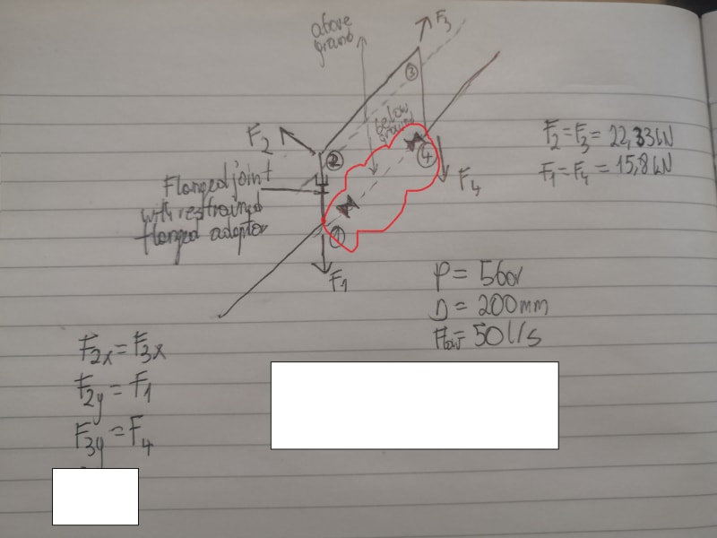
I am trying to analyse segment of the pipe as per attached sketch. I drew a simplified thrust force diagram from system pressure and mass flow. Between point 1 and 2 there is a restrained flange adaptor or flanged joint. Would I need to consider longitudinal stress coming from bending moment as a result of F2x acting on lever arm between point 2 and this flanged joint? The horizontal part of force F3 (F3x) seems to counterbalance the force F2x which would give me a bending moment.

Thanks a lot!
 
 https://files.engineering.com/getfile.aspx?folder=2d0bbc55-1ee3-451c-b877-48724c1df5f1&file=IMG_20210419_142223.jpg
Replies continue below

Recommended for you

20210420_121904_sfkzfz.jpg


Your joint elbow thrust loads are balanced by tension created in the pipe. That will elongate the pipes. The elongation create displacements at the joints which will introduce secondary bending moments.
 
Hi ANDREW,

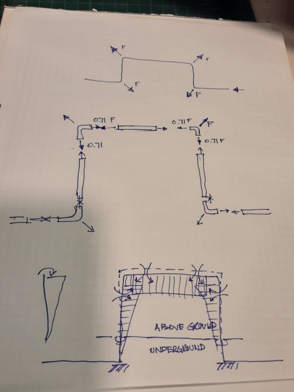
What is the dashed line at underground section btw. points 1 and 4 and the valves ? If the dashed line is a by-pass pipe conn. btw. 1 and 4, and these connections constructed with Tee, no moment will develop at above section and so at flanged adaptor..

IMG_Rev_20210419_142223_odiz4w.jpg
 
Hi both,

HTURKAK,
Dashed line shows permanent line that is isolated. The bypass line is between 1-2-3-4.

1503-44,
I must say that is a rather unique nickname!
Thank you for your sketch and good explanation.

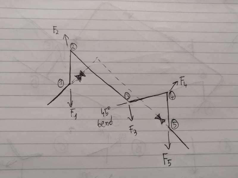
What would happen if I had a bit more complicated temporary pipeline as per the file below? Temporary line is between points 1-2-3-4-5. However, this time there is an additional 45 bend and pipework between bends 2 and 4 is made of HDPE (electrofused) as oppposed to the rest that is ductile iron. The horizontal part of the force F2 will be much larger then opposite force coming from F3. How to get pipe 2-3 elongation if it has forces of different magnitude at both ends?


IMG_20210421_094629_dvh60q.jpg


Thanks again,
Andrew
 
Andrew, you didn't mention the pipe material before. The Welded steel pipe I assumed it was may act differently than ductile iron. The type of joining is also important. How are the pipes connected? Push-in, glued, fused, mechanical clamps? Some are very limited and won't take any pipe tension.

Generally adding turns and offset angles can decrease pipe forces, since the pipe has more freedom to flex and thereby release stress. The more rigid these are, the more stress results. Flexibility decreases stress, but allows more movement.

First I need to know more about the joining method. The only way to have tension in the pipe working for us is to have joints that will not separate and pull apart. Otherwise we will have to find a different way to ensure that won't happen.

 
1503-44, The ductile iron pipe between points 1 and 2 has one end load restrained flange adaptor, same between 4 and 5. The bends in points 2 and 4 and flanged ductile iron. The PE pipe (2-3 and 3-4) is electrofused and connected to DI bends with stub ends. The 45 bend is also electrofused. Pipework is fully restrained. My only worry are possible bending moments acting on flange adaptor/flanges on vertical legs.

 
OK so 2 to 4 is HDPE pipe. Rest is DI.
THE HDPE is very flexible in relation to the DI and the geometry is much more flexible as well.

Can you tell me the lengths between bends and diameters of the pipes.
And,
What magnitude of forces are we talking about here?

I think we can consider the iron pipe as rigid, let the HDPE transfer its load to the DI risers and see what the bending moments look like in the risers.
 
Yes, I fully agree that DI can be regarded as rigid in the setting and that PE pipe will elongate/slightly move due to thrust.
All pipework (DI and PE)have internal diameter of about 300mm. All are rated for 16 bars (including restrained flange adaptor).
Between 2-3 the pipe is about 8m long
Between 3-4 about 10m long
Vertical legs are about 2m long with flange adaptor in the middle.

The load will just from hydrostatic part of thrust @10 bar as mass flow is negligible (70kg/s).

 
Oh. I didnt realise the pipes were that long. I thought maybe a few m. I'd plan on putting in at least two supports under the HDPE, one 5m from J2 and another 7m from J4. You can do that I hope, because 18m with a horizontal bend in the middle that could sag a lot, would put a lot more moment than I expected on those risers. 2 additional supports??
 
Yes, pipe will be properly supported as required by the manufacturer - probably sandbags which should allow for pipe movement and won't make it rigid.

I am still not sure how to investigate bending moment on vertical segments in easy way. If I were to consider that F2x force is about 113.1 kN and the opposite force on 45 bend F3x is 33.1 kN I get 80 kN of force that acts on bend 2. That is quite a lot to be taken by a flanged joint (80kNm) so thinking how I could prove that it is way too conservative and joint can take it...

Thank you,
Andrew
 
That's great. Lets try to get the loads down.

So now we can consider that all Vertical plane loads are all taken by your sand bag supports and balanced tension in the pipe. No weight or vertical moments ate created at the risers by any pipe spans.

Considering horiz loads.

Almost all of the load at the joints will be balanced by tension in the pipe.

Secondary load

In the plan view, j3 will move to SW as pipes 23 and 34 elongate. That will place a torsional CW moment on riser 2 and an equal, but CCW moment on j4. An equal moment will be created in the pipes 234. Shear will be small due to the long lengths.

The movement at 3 will be reduced by some opposite movement at 2 and 4. The key concept is that, due to the long pipe's flexing, there is no great resistance to develope much force at the risers. If you considered the pipe 23 as a beam, fixed at j2, the reaction caused at 2 by a deflection at 3 would be small and that is the only force that is unbalanced at j2.

And that is the same story at j4. A small reaction caused by elongation at j3, plus the torsional CCW moment are resisted by the riser.

We can now estimate the reactions at the risers and the moment in the pipes. Calculate the elongation of both HDPE pipes. Convert that to an "equivalent" movement perpendicular to each pipe end. You now have some estimate of how much a cantilever beam 23 would deflect at its free end j3 when held by a rigid anchor at j2. We know that Deflection at the free end of a cantilever beam is Defl = PL^3/(3EI) so solve for load P, and that is the reaction at the support. Moment in the pipe is P x L. But realising that the support is not totally rigid, we can allow some movement there and reduce P some. Let's say by 40%. ?? So now the unbalanced load at j2 is 0.6 x P and pipe moment is 0.6 x M. M is torsion in the riser and 0.6P is the load at the top of the riser. See if you agree with my 0.6 factor. I just guessed it would be reasonable.

Consider the bottom of the riser a fixed support and calculate the moment caused by 0.6P at the flange. Do the same at riser 4.

If you can get a copy of ASME B31.1, there is quite a bit in there about how to go about rough estimating pipe stresses. Its good reading.

 
1503-44,
Thank you a lot for detailed explanation.

Could you please explain why most of the horizontal load would be balanced by a tension in the pipe? For example, the thrust along pipe 2-3 at point 2 is much higher than thrust at point 3 (especially force thrust component along the pipe) so I struggle to see how they balance out and would appreciate if you can describe it in a bit more detail.

 
First, momentum forces are generated by flowing mass changing direction at elbows. There are no momentum forces in straight pipe between elbows, because there is no change of the mass x velocity vectors. So all momentum forces are placed at joints only. Since axial force in a pipe can be resisted by both tension and compression in the pipe wall as needed, an axial force placed at the middle of pipe 2-3 in the direction of 2 to 3, half will be transferred to j2 by pipe tension and the other half to j3 by pipe compression. To be more accurate, the distribution to each joint should be adjusted, depending on distance from load to each joint. A load placed at 1/4 pipe length from j2 should have 75% of that force transferred to j2 and 25% transferred to j3.

You can also have unbalanced pressure forces generated at elbows. Pressure force = pipe pressure x area of pipe. 10 psi pipe pressure in a pipe with 100 in2 of internal area generates a 1000 lb force. At joint 2 1000lb is applied on the joint horizontally with direction of 3 to 2. There is another 1000lb force from pipe 1-2 that is applied at j2, vertically up. Those forces are basically resisted by pipe tension, just as the momentum forces are. Tension in pipe 2-3 resists the horizontal pressure force at j2 and tension in pipe 1-2 resists the vertical force at j2. The tension in pipe 1-2 is balanced by a similar pressure force acting downward at joint 1. You can see that our balancing procedure is the same as what we did for the momentum forces.

To consider both pressure and momentum forces at the same time, just add all horiz force components together and all vertical forces together and balance one, then the other.

In the case of joint 3, or anywhere a joint has a force imbalance, we have to assume that bending moments will form up inside the pipe that will resist all forces that remains unbalanced by pipe axial force. Basically the unbalanced forces are resolved into shear forces acting perpendicular to pipe axes. The bending moment can be estimated by the shear force x pipe length.

You have to remember that we are trying to do this force distribution in a pipe structure that is usually very much indeterminate and we are making a lot of simplifying assumptions, so solutions are not exact and all forces and moments might not balance exactly. The goal is to reasonably reach a conservative, most probable, and plausible solution. It may take several iterations to develop a conclusion, redistributing any unbalanced forces and moments as you move from one iteration to the next. It helps if you know the basic principles of structural analysis, as pipe is a space frame, just made of "O-beams". Knowing how the structural analysis moment distribution method works is advantageous. I was a structural engineer before I started doing pipe stress.
 
And last. There is another pipe force caused by internal pressure expansion of the pipe diameter and internal pressure acting on the inside of pipe end caps, or closed valves.

Diameter expansion from internal pressure creates an axial pipe tension force, due to the Poison effect. Axial pipe stress in the pipe wall is Poison Ratio of the pipe material x the hoop stress in the pipe caused by the internal pressure. Generally, P-ratio is 0.25 to 0.3, so an axial tension force is created in the pipe in addition to the above, from internal pressure.

With all the above, you can see why pipe stress is usually done with computer assistance.
 
1503-44

Thank you again for detailed explanation. I know two other methods to solve indeterminate systems but this one is new so have familiarised myself with it.

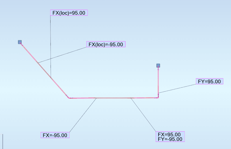
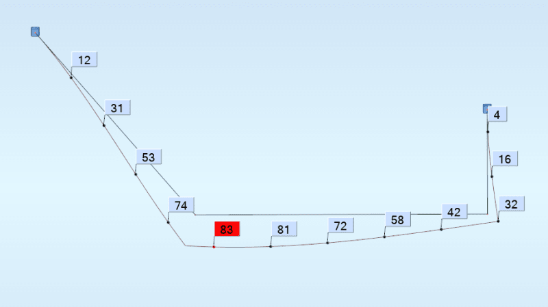
As you suggested, I modelled a pipe as a space frame using tubular section and PE100 properties and assumed that pipeline is fixed at both ends ( rigid DI risers). The beams are modelled as members on elastic ground.

I assigned following loadings based on 16 bar pressure (overkill but conservative):
loads_db1qvh.png


Based on above I obtained following displacements , which are as expected based on earlier discussion:
displacements_qri2ia.png


The normal stress for this scenario is about 5 MPa which is much lower than PE pipe tensile strength of above 20 MPa. Resulting moments and forces are also very low as pipe doesn't offer much resistance (it deflects).

I know I didn't take into account thermal stress but here pipe is free to move so again I believe this can be neglected. The Poisson effect would probably increase tension in the pipe but this again should be low.

Please, let me know whether my conclusion are correct.
 
I can't check your math, but the diagram looks absolutely perfect.
You are good to go.
 
Thanks a lot for the tips and the time you devoted to this topic ![thumbsup2]
 
You are Welcome.
It is satisfying for me to know that you picked this subject up so quickly. Well done.
 
Status
Not open for further replies.

Part and Inventory Search

Sponsor