Continue to Site

Eng-Tips is the largest engineering community on the Internet

Intelligent Work Forums for Engineering Professionals

  • Congratulations KootK on being selected by the Eng-Tips community for having the most helpful posts in the forums last week. Way to Go!

Bending in weak axis: multiple thin plates stronger than one thick plate ??? S(thin) = 4x S(thick) 1

Status
Not open for further replies.

TpaRAF2

Structural
Feb 6, 2019
3
Here's an odd puzzle I've encountered. I must be missing something, as the calcs do not match 'common sense' (IMO).

I am reviewing bending of a flat steel bar about the weak axis. Very straight forward to determine I, y and then S.

If I compare using multiple, thin flat bars (same width that add up to the same thickness), the value for the composite I and S are 4 times _greater_ than the single thick bar. This was computed using parallel axis theorem [I= Σ(Io + A·d²]. The thin plates are adequately connected to resist sliding or separating.

A bit of surfing the web results in a lot of composite material topics, and CLPT (classical laminated plate theory). Therein, examples and discussions seem to point to reduced deflection for laminated plates being about 25% of the equivalent sold plate. This matches my calcs suggesting a 4x increase in mom't of inertia.

The underlying assumption for this case, in CLPT and in PAT is the layers don't slip past each other. The proposed stack is stitch fastened, so layers don't slip.

This increase in section modulus is just not logical to me. The stacked bars should be weaker than the equivalent solid bar. If not, we'd be making durn near every thick flange steel beam out of stacks of thinner plates.

Thanks for your help and guidance on this puzzling observation.
 
Replies continue below

Recommended for you

You must be doing something wrong.

The calculations should give exactly the same result.

Can you give some example references showing 25% deflection for laminated plates?

Doug Jenkins
Interactive Design Services
 
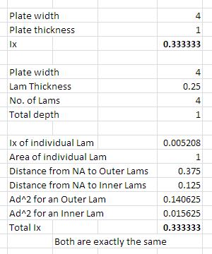
I get exactly the same for solid vs. a 4 Lam plate:
IX_Lams_wp1pde.jpg


Check out Eng-Tips Forum's Policies here:
faq731-376
 
here is what I get for a solid 12x6 and then the same broken into 2 unit layers:
Python:
Solid 12x6 Pl:
Area = 72.0
Cx = 6.0
Cy = 3.0
Global Axis: = ---
Ix = 864.0
Iy = 3456.0
Ixy = 1296.0
Jz = 4320.0
Sx,top = 288.0
Sx,botom = 288.0
Sy,right = 576.0
Sy,left = 576.0
rx = 3.46410161514
ry = 6.92820323028
rz = 7.74596669241
Shape Centroidal Axis: = --
Ixx = 216.0
Iyy = 864.0
Ixxyy = 0.0
Jzz = 1080.0
Sxx,top = 72.0
Sxx,bottom = 72.0
Syy,right = 144.0
Syy,left = 144.0
rxx = 1.73205080757
ryy = 3.46410161514
rzz = 3.87298334621
Shape Principal Axis: = --
Iuu = 216.0
Ivv = 864.0
Iuuvv = 0.0
Theta1,u = -90.0
Theta2,v = 0.0
--
Layer 1 - 12 x 2 at elevation 0:--
Area = 24.0
Cx = 6.0
Cy = 1.0
Global Axis: = ---
Ix = 32.0
Iy = 1152.0
Ixy = 144.0
Jz = 1184.0
Sx,top = 32.0
Sx,botom = 32.0
Sy,right = 192.0
Sy,left = 192.0
rx = 1.15470053838
ry = 6.92820323028
rz = 7.02376916857
Shape Centroidal Axis: = --
Ixx = 8.0
Iyy = 288.0
Ixxyy = 0.0
Jzz = 296.0
Sxx,top = 8.0
Sxx,bottom = 8.0
Syy,right = 48.0
Syy,left = 48.0
rxx = 0.57735026919
ryy = 3.46410161514
rzz = 3.51188458428
Shape Principal Axis: = --
Iuu = 8.0
Ivv = 288.0
Iuuvv = 0.0
Theta1,u = -90.0
Theta2,v = 0.0
--
Layer 2 - 12 x 2 at elevation 2:--
Area = 24.0
Cx = 6.0
Cy = 3.0
Global Axis: = ---
Ix = 224.0
Iy = 1152.0
Ixy = 432.0
Jz = 1376.0
Sx,top = 224.0
Sx,botom = 224.0
Sy,right = 192.0
Sy,left = 192.0
rx = 3.0550504633
ry = 6.92820323028
rz = 7.5718777944
Shape Centroidal Axis: = --
Ixx = 8.0
Iyy = 288.0
Ixxyy = 0.0
Jzz = 296.0
Sxx,top = 8.0
Sxx,bottom = 8.0
Syy,right = 48.0
Syy,left = 48.0
rxx = 0.57735026919
ryy = 3.46410161514
rzz = 3.51188458428
Shape Principal Axis: = --
Iuu = 8.0
Ivv = 288.0
Iuuvv = 0.0
Theta1,u = -90.0
Theta2,v = 0.0
--
Layer 3 - 12 x 2 at elevation 4:--
Area = 24.0
Cx = 6.0
Cy = 5.0
Global Axis: = ---
Ix = 608.0
Iy = 1152.0
Ixy = 720.0
Jz = 1760.0
Sx,top = 608.0
Sx,botom = 608.0
Sy,right = 192.0
Sy,left = 192.0
rx = 5.03322295685
ry = 6.92820323028
rz = 8.56348838578
Shape Centroidal Axis: = --
Ixx = 8.0
Iyy = 288.0
Ixxyy = 0.0
Jzz = 296.0
Sxx,top = 8.0
Sxx,bottom = 8.0
Syy,right = 48.0
Syy,left = 48.0
rxx = 0.57735026919
ryy = 3.46410161514
rzz = 3.51188458428
Shape Principal Axis: = --
Iuu = 8.0
Ivv = 288.0
Iuuvv = 0.0
Theta1,u = -90.0
Theta2,v = 0.0

**Composite of the Plate Layers:**
Area = 72.0
cx = 6.0
cy = 3.0
Shape Centroidal Axis: = --
Ix = 216.0
Iy = 864.0
Ixy = 0.0
Jz = 1080.0
rx = 1.73205080757
ry = 3.46410161514
rz = 3.87298334621
Shape Principal Axis: = --
Iu = 216.0
Iv = 864.0
Iuv = 0.0
theta,u = -90.0
theta,v = 0.0
Jw = 1080.0
ru = 1.73205080757
rv = 3.46410161514
rw = 3.87298334621
Edit: had a pointer wrong in the output now its right. and as other have noted should result in the same values
Open Source Structural Applications:
 
To the OP -

If you lead off a topic with "I found some inexplicable stuff on the web" and don't include a link to those locations, then there is no reasonable answer to any subsequent question.
 
Depends on how those 4x thin slabs are sliding between each other so they act as 4 independent thin bending plates, or are they welded completely through so they act as ONE UNIT?

Only in pure tension applied end-to-end, or a shear force with absolutely 0.00 space between plates will the 4x thin independent plates yield an equal resistance to a single plate 4x thick.
 
From the OP:

The thin plates are adequately connected to resist sliding or separating.

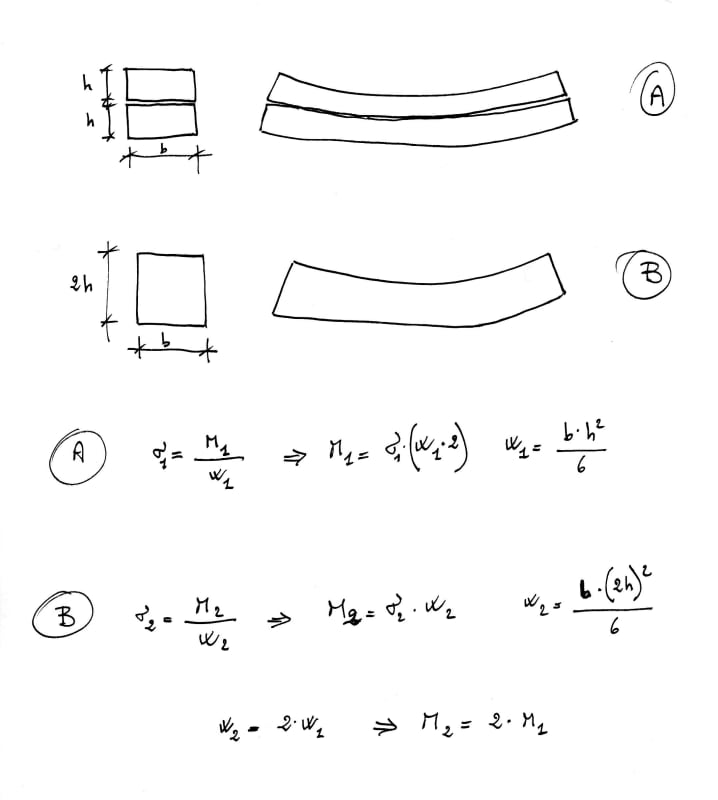
robyengIT - I'm not sure what your calcs are supposed to show, but it looks like you are comparing stresses in plates that are free to slide, rather than deflections in plates that are not free to slide.

Doug Jenkins
Interactive Design Services
 
Yes, right. A : plates free to slide B : plates connected or solid section
Results are same for solid section and plates only if plates are connected to resist sliding or separating
 
Yes, right. A : plates free to slide B : plates connected or solid section
Results are same for solid section and plates only if plates are connected to resist sliding or separating

No-one has suggested otherwise.

Doug Jenkins
Interactive Design Services
 
I just wanted to explain the calculation in a simple way to the OP
 
Raf,

Are you saying for example you have a single 4" wide x 1" tall bar. Then you have four bars that are 4" wide and 1/4" tall that create the same size shape as the single 4x1? The 4 single 1/4" bars are weaker and deflect more than the solid 4"x1" UNLESS they are bonded together to prevent slip. Bonded together, they should behave the same as the 4"x1".
 
One 4x1 plate
I=4x1^3/12=0.333
Four 4x0.25 plate
I=(1x0.25^3/12)x4=0.005
There is no bonding among the contact surface of the plates. Therefore the total moment inertia for the four plate is the sum of the moment inertia of each plate.
 
Shu Jiang, for 4 each 0.25" thick, stacked plates, 4" wide, not fastended together, I = 4ea. x (b x h[sup]3[/sup])/12 = 4 x 4 x 0.25[sup]3[/sup]/12 = 0.02083 in[sup]4[/sup], not 0.005 in[sup]4[/sup]. b = 4" not 1".

 
1) but I/y is 0.67in3 for monolithic slab and 0.166in3 for 4 plies (the factor of 4 cal'd above)
2) but OP says the plies are "glued" together
3) I think the OP's error is that stress for 4 unglued plies is 4 times the stress of either the slab or 4 glued together plys. As IDS posted "you must have done something wrong".

another day in paradise, or is paradise one day closer ?
 
I think the OP's mistake was possibly in the calculation of "d" for some or all of the plates for use in the parallel axis theorem. It's the distance from the NA of the whole to the NA of each component, thus "d" for the interior plies is 0.125" and 0.375" for the exterior plies. Worked for me; I get Ix = 0.3333 in^4 if the plies are fully connected.

Perhaps we could hear from the OP - have you found your error?
 
The Section Modulus varies by the square of the thickness.

The Moment of Inertia varies by the cube of the thickness.

Not all people's "common sense" yield the same answer.
 
I think "d" for 4 plies separately bending (ie not glued) is the same for each ply, with each ply carrying 1/4 of the applied moment.

I understand that the curvature of each ply is slightly different (each ply should be 0.25" different) but this should be a small 2nd order difference.

another day in paradise, or is paradise one day closer ?
 
"I think 'd' for 4 plies separately bending (ie not glued) is the same for each ply,"

Of course. I don't think anyone would argue otherwise. If that was in response to my post, I was considering the case where the plates are completely and fully bonded, which for steel plates would be nearly impossible to achieve in the 'real world'.

"with each ply carrying 1/4 of the applied moment."

Approximately, give or take some negligible variations due to friction between the plates and even more negligible differences in modulus of elasticity.

 
I think the OP's mistake was possibly in the calculation of "d" for some or all of the plates for use in the parallel axis theorem

Yes, I think that must be it. I suspect what he was doing was taking the distance for the parallel axis component as the distance between the centroids of each pair of plates, rather than the distance from the centre of the plate to the overall centroid.

I'd still like to know what information he has found on-line that suggests the "glued" 4 ply beam will have greater stiffness than a single ply beam with the same overall dimensions.

Incidentally, the case of the sliding plates is totally irrelevant to the original question, but it has been discussed in detail here, and the assumption of equal load distribution between the layers is at best a very rough approximation.

Doug Jenkins
Interactive Design Services
 
Status
Not open for further replies.

Part and Inventory Search

Sponsor