Eng-Tips is the largest engineering community on the Internet

Intelligent Work Forums for Engineering Professionals

Best way to mesh rocket fin in Abaqus

Status
Not open for further replies.

aerolad7

Aerospace
Nov 15, 2023
5
0
0
US
Hi,

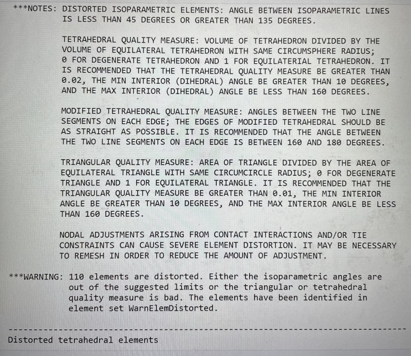
I would like to conduct a frequency analysis on the following fin in Abaqus.
fin2_birpbz.png
Fin1_mhvde7.png


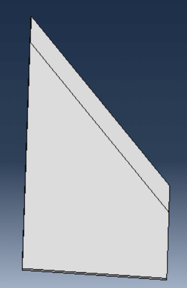
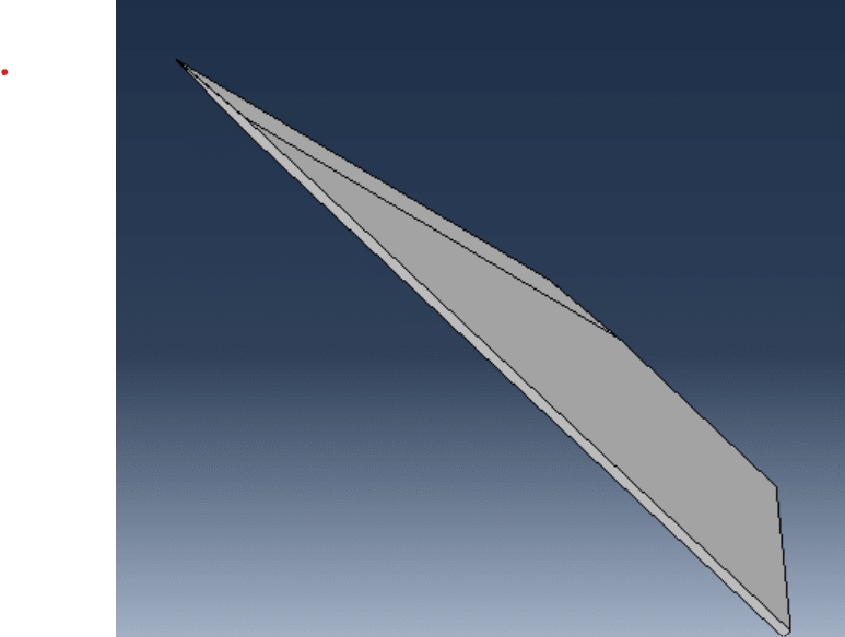
In the mesh module > mesh controls Abaqus only lets me use a Tet mesh (or a bottom up Hex). However, if I mesh with tetrahedral elements I get a very bad aspect ratio for the elements on the leading edge of the fin geometry
fin3_veagkg.png


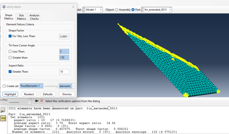
Making the mesh finer reduces the aspect ratio, but is not a viable solution because it would need to be incredibly fine. If I run the simulation I get the error that these elements are distorted.

How should I attempt to solve this issue / what is the best way to mesh this part? Would this issue be resolved with hexahedral elements? Can the geometry be partitioned?

My thinking is that the edge is so thin and that is causing the huge aspect ratio.

Thank you.
 
Replies continue below

Recommended for you

You can use volume (cell) partitions but you might be left with a tip that can’t be meshed with hex elements. You could make that tip small and apply tetrahedral mesh there. Abaqus will automatically connect it with hex elements using tie constraint.
 
What does the geometry of the leading edge look like? Is it modeled as a zero thickness knife edge or is there a small flat/radius at the edge?
 
This is just a warning, the analysis will run with it. In fact, there are some elements described as distorted in most analyses. You should just make sure that they don’t have significant impact on the results (it matters where they are located) and that they aren’t distorted too much (visual check usually helps).
 
It's modeled as a knife edge.

I am newer to FEA and meshing - when you say make sure that they aren't distorted too much, what should I look for visually e.g. for a tetrahedral element that would tell me that it is too distorted? More to the verify mesh tool, is the aspect ratio critical i.e. is there a value I should be aiming for?

Thanks a lot for your help.
 
Use a shell element model. Will work perfectly fine (better) for stiffness/frequency analysis.

Do not use a solid element model for this thin thing. Most solid elements are bad in bending, and particularly when there is only one element thru the thickness. If you insist on a solid model use a solid shell element that has good bending performance. There is a section somewhere in the Abaqus documentation showing element performance in bending.

And whatever you do, DO NOT use 4 noded tet elements - they are awful.
 
I second the proposal for 2D elements, especially if you have only 1 TET through the thickness. I do hear OP asking "how do I model my (zero thickness) knife edge ?"

"Hoffen wir mal, dass alles gut geht !"
General Paulus, Nov 1942, outside Stalingrad after the launch of Operation Uranus.
 
This might be moot if you go with shells but you can also partition it into smaller, more regularly shaped areas/volumes that will mesh better. That will definitely help.
 
Shells can make sense but it will be tricky to apply proper variable thickness to them. It will requore some work but is possible in Abaqus.
 
This is just my intuition, but it seems to me that different approaches to modeling a sharp edge will affect the result to a lesser extent than the choice of constraints a given fin.
You can model it separately by constraining one of the edges, or you can also include into mesh a simplified portion of the structure to which this fin is attached, and the differences between these two options in terms of the first natural frequency will be even greater than between the option with a correctly modeled sharp edge and the option when this sharp edge was not modeled at all.
 
is it really necessary to model ALL the fin ? How is the fin being made ?? Will the real shape have a razor sharp edge ??

"Hoffen wir mal, dass alles gut geht !"
General Paulus, Nov 1942, outside Stalingrad after the launch of Operation Uranus.
 
If you're going to keep this as a solid model (as opposed to the surface model being suggested by others, which is probably a good idea), I'd reconsider modeling the leading edge as a zero thickness knife edge. At the angle you're dealing with, the zero thickness edge is going to lead to distorted elements at the edge. If you can truncate it with a flat face at the leading edge, that would at least make it possible to get a decent element there, if you make the mesh fine enough (although this might require an overly fine mesh). Plus, it probably better reflects reality anyways.
 
likely. but somewhat depends on how the fin is attached. and might be slightly on the conservative side as there will be a bit more mass with constant thickness model vs actual part.
 
Status
Not open for further replies.
Back
Top