Continue to Site

Eng-Tips is the largest engineering community on the Internet

Intelligent Work Forums for Engineering Professionals

  • Congratulations MintJulep on being selected by the Eng-Tips community for having the most helpful posts in the forums last week. Way to Go!

Big difference in moment capacity of RC beam for Static vs. Explicit dynamic analysis?

Status
Not open for further replies.

W1nther

Civil/Environmental
Nov 28, 2019
9
Hi
I'm trying to model progressive collapse of a reinforced concrete building and to be sure my materials behave as I expect I have created a simply supported beam where I load it until failure.
I hoped that I would see the moment capacity of the beam at least be the same as my analytical calculations but my dynamic model did not even come close to my estimate so I created the same model but this time as a static analysis.

Moment capacity:
Based on analytical calculations - 373 kNm
Static analysis - 378 kNm
Dynamic Explicit - 311 kNm (loaded linearly over 10 sec, dynamic amplification should be neglible)

Almost identical models. Of course there are a few differences like element types are changed to explicit in the dynamic analysis and so on but nothing that should affect the results this much.

Can anyone explain why there is such a big difference between the static and dynamic model?
Any help is appreciated.
I can of course also upload my .cae or .inp files if anyone is willing to take a look at it?
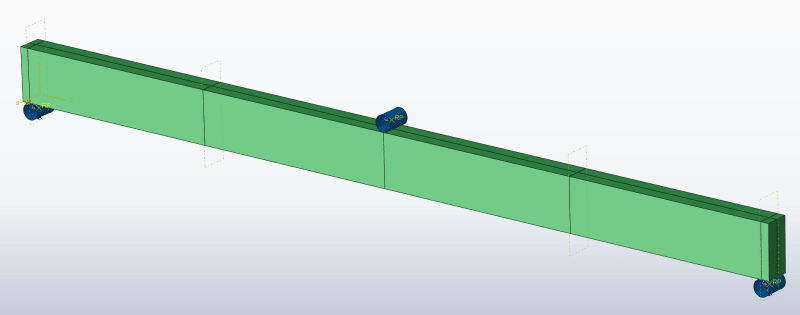
ThreePointBending_xnbehe.png


It is modelled as a 3 point bending test and I put shear reinforcement in so I was sure it wouldn't fail due to shear forces.

Michael
 
Replies continue below

Recommended for you

Please upload the model’s files (cae or inp). Such discrepancies may have various reasons and it’s necessary to take a closer look at the settings and results. It’s very important to check reaction forces and energies, these can indicate problems with solution accuracy, especially in Explicit. I suspect that mesh, element type and contact might be the reason here.
 
Hi FEA Way

I didn't know contact could have a big impact, I removed it entirely in my static model and just used displacement BC since I couldn't get contact to work like in my dynamic analysis. Anyway here is my CAE file.
You can probably use a coarser mesh than me, I just hoped my results would improve with a finer mesh.
 
 https://files.engineering.com/getfile.aspx?folder=3f1de0f7-b0c7-4a3e-8a7d-c05e61c7babe&file=BeamCDP_ShellSolidV7.cae
Just in case it is helpful here are some numbers:
Calculated moment capacity: 373 kNm

Moment at middle(L/2) from dead load: 59,4 kNm
Moment from full load over 10 sec: 140kN -->(PL/4) 350 kNm
Total = 409,4 at 10 sec
 
The settings of both models look correct. Unfortunately I can’t run these models with fine mesh in reasonable time due to limited computational resources. And it doesn’t make sense to run this with very coarse mesh (too large impact on results plus convergence issues). Thus I will give you some advice how to check the correctness of these results.

You should solve both models (implicit and explicit) with the same assumptions (both with contact or both with boundary conditions in place of contact). Then check reaction forces in supports and verify energies. This is very important, especially in Explicit. Start from comparing ALLAE vs ALLIE (hourglassing). Since you use automatic stabilization in Standard, you should also check ALLSD vs ALLIE. ETOTAL energy needs to be approximately constant and zero throughout the analysis. In Explicit simulation with contact ALLPW energy has to be close to zero. Since in Explicit you are performing quasi-static analysis, ALLKE should be small when compared with ALLIE.
 
Okay, thank you very much. I will look at all of these things. Sometimes I feel like the Abaqus user guide could be better at explaining such things, especially for someone doing explicit dynamic analysis for the first time.

Can I ask you how you would go about modelling the dynamics of progressive collapse for a larger part of a building? I have access to a fairly fast computer but I really want to simplify my model to save some time.
Someone recommended using ordinary shell elements but then I can not use embedded rebar. I tried using continuum shell elements but that did not seem much faster than using solids. Something that's important to me is that I can simulate different kind of failure of a beam and then see how that failure develops and how that would affect the floor below when it gets impacted with the debris from above.
 
It’s possible to define reinforcement for shell elements using rebar feature (in shell section editor there is an option called Rebar Layers). Check the article "Nonlinear analysis on progressive collapse of tall steel composite buildings" by R. Rahnavard et al. for reference.
 
Status
Not open for further replies.

Part and Inventory Search

Sponsor