Continue to Site

Eng-Tips is the largest engineering community on the Internet

Intelligent Work Forums for Engineering Professionals

  • Congratulations Toost on being selected by the Eng-Tips community for having the most helpful posts in the forums last week. Way to Go!

Bimetallic Beam Deflections 2

Status
Not open for further replies.

numbersguy123

Structural
Nov 13, 2019
4
Hello everyone,

I'm trying to analyze the behavior of 2 bimetallic materials driven by a temperature load. I am having some issues trying to validate my calculations and FEA simulations, so I'm seeking help. Here's what I have done and let me know if you have any suggestions to improve my methods:

I have a steel sheet (0.03" thick) and AL (0.09" thick) plate that are permanently pressed/joined together. Both are roughly 18" long and 12" wide. The metals are being cooled by 102 deg F, so there is stress build up due to the CTE mismatch. AL will shrink more so it will also deflect. My main issue is trying to

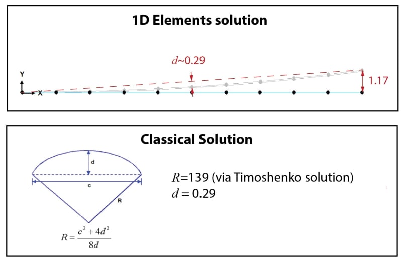
I found that there is a radius of curvature equation derived nicely in this wiki page for bimetallic materials:
I went through the calculations, and got a radius of curvature value which eventually allowed me to see how far the composite beam is deflecting assuming it's fixed on one end.

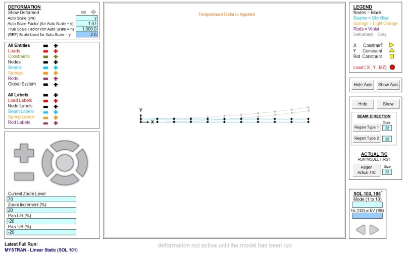
I am using FEMAP to model this problem but the deflection values do not match up to analytical solutions so now I'm have doubts in both my modeling and my calculations. I modeled the metals using solids elements in one case and plate elements in the other. Plate deflections are a bit closer (4.61") while solid deflections are lower at 1.92", assuming my analytical prediction is correct for deflection = 3.85". I'm interested in deflection, but more importantly, the stresses at the interface.

I used Membrane elements as well, but I didn't get good results, sine most of the deflection is 2D. I also tried using 3-2-1 constraint method to see how the piece would naturally deform given the temperature load, but it's something I just learned and I don't have a good way to validate the results, since the boundary conditions are tricky in this regard.

Any suggestions on how to match model results to calculations? Thanks for your help!
 
Replies continue below

Recommended for you

First of all make sure that all dimensions and material property units are correct. This is common reason of mismatch between analytical and numerical results. Also what are your initial and boundary conditions for the thermal part ? How do you apply temperature difference ? Did you define temperature at zero strain correctly ?

By the way, where did you learn about 3-2-1 method ? In some book or article ? I'm asking out of curiosity because this approach is rarely mentioned in literature.
 
yup I made sure the units match and are consistent. The initial temp for the part is at room temp (73F) and the applied temp load is -29F (body load). I have an entire surface fixed on one end.

Here is the 3-2-1 method I came across:

I have uploaded a picture of one of the results file. It shows the constraint and deflections. Hopefully that makes it easier to understand. Thanks.
 
Another important factor is how both parts of the beam are connected (mechanically as well as thermally). Is it perfect connection (bonded/tied contact and thermal interface without resistance) ?

Thanks for the link. That's where I've read about this method too. Still haven't tried it though.
 
I think membranes should not be good, as you suggest.

I'd've thought 3D elements would be best, better than plate elements.
How many elements through the thickness ? 3 ?
How did you join the two plates ? common nodes (same node just for Al and Steel strips) or coincident nodes (joined with a CBUSH) ?

Is your CTE in the right units (per deg F) ?

I don't think 3-2-1 is the right constraint for this, since you want to react bending. I'd constrain all nodes in the axial direction, 2 in the up direction, and 1 in the lateral. This will constrain the bending at the base but not over constrain (Poisson effects).


another day in paradise, or is paradise one day closer ?
 
18" x 12"? Sounds like you are dealing with a plate rather than a strip - the strip formula may not apply in your case.
 
OPTION 1: Seems like this can easily be done as a "2D Solid". You model the cross section (the section shown in the upper right picture from the Wikipedia link) with quad elements. It should be easy to mesh and at the interface the nodes will be shared (essentially perfectly bonded). The effect of the Z-direction (in and out of the page in this case) is captured by selecting either plane stress or plane strain (a strip would be plane stress and wide plate might be closer to plane strain). You can run both solutions to create the outer limits (thought they won't be that much different). In this case, it is probably about half way in-between.

OPTION 2 (Deflection only): You might be able to model this with beam elements (but this won't give you the interface stresses unfortunately). I used the "1D Elements" program (link below) and also included an image. The deformed shape appears to be correct. The beam elements would be separated by the distance between the CG's of each strip. And each strip would be connected by stiff beam elements.


bimetallic_strip_vepgpk.jpg


EDIT: I ran a real model with the 1D Elements program and compared it to the Timoshenko solution. The deflections were within about 3% of eachother. I would probably need to double check it though.


Brian
 
Thank you Brian. I made a similar model using beams and the results look pretty similar to yours. How did you arrive at d=0.29? It seems like if I pick a midpoint on the beam, the deflection is about half of the max which would be d=0.6, so I'm a little confused.

I have stress values from both solid and plate models. I will do a comparison once I finalize the deflections.

Appreciate your help.
 
 https://files.engineering.com/getfile.aspx?folder=97e2113e-8629-4312-a543-02583103bac9&file=beam_model_results.png
To get the most accurate "d", you might have to do some additional math. In my case, I just used the Y-component, which should be rather close (neglecting the X-component deformation and assuming small deformation). That is why I put a "~" by the d.

Looking at the dotted orange line in my picture, the Y-position is 1.17/2 at the midspan (0.585). The Y-position on of the node at the midspan is 0.292 (for my model at least). So d is about 0.585-0.292 = 0.293. I used a "c" of 18.0 btw.

You should be able to use 2D Solid elements in a state of plane stress (or just shell elements where there is no out-of-plane bending) to provide another data point (and add further validation to the results). However, you will need about 3 (or more) elements through the thickness for each metal strip (should be the Y-direction in your model) because you need to capture the bending effect. Because it is very thin, and because there are aspect ratio limitations, there will be quite a few quad elements (you might be able to use 2 elements through the thickness if they are higher order). So expect it to be several thousand elements. You might consider a smaller test model (maybe an inch long) since the radius of curvature and interfaces should not be affected by length (at least for the 2D Solid model)

Note that the stresses for the actual 3D problem can be significantly affected by the boundary condition at the constraint. There are two effects (restraining the anticlastic curvature) and restraining the Poisson contraction/expansion in and out of the page (depending on the actual constraint conditions). As you get farther from the constraint, these effects will dissipate. To accurately capture this would require 3D solid elements....and lots of them. You should probably estimate the DOF first to see what you are up against.

Brian
 
Hello Brian,

I took a few days off and now I'm ready to look at this again. Thanks for your input on the d calculations. I realized my mistake was measuring d from the unformed original shape instead of the red dotted line. It makes sense now. I realized a good approximation of max deflection/4 also works pretty well for these cases. For your classical solution, how did you obtain the d or the R? I'm assuming this is independent of the model results. I get that once you have either d or the R, you can obtain the other using the equation in your pic, but I'm not sure I follow how one of them is obtained? If I used the bimetallic beam equation I linked above, I get R=101.67, which means d=0.97. I can't trust my hand calc since it's so far off...

Thanks.
 
Try with equations provided in the Roark’s Formulas for Stress and Strain if you have access to this book. There’s a nice chapter about bimetallic strips.
 
Status
Not open for further replies.

Part and Inventory Search

Sponsor