Eng-Tips is the largest engineering community on the Internet

Intelligent Work Forums for Engineering Professionals

  • Congratulations waross on being selected by the Tek-Tips community for having the most helpful posts in the forums last week. Way to Go!

bladder accumulator/bi-rotational pump/single acting cylinder closed loop system 3

Status
Not open for further replies.

guatom

Industrial
Aug 30, 2008
7
0
0
GT
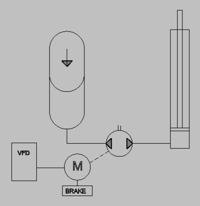
The application is raising and lowering a 4000# vertical load approximately 20" once every 120 seconds, 10 seconds to extend 20" and 10 seconds to retract 20", 100 seconds dwell. An accumulator is charged with nitrogen to approx 320 psi to offset the load produced by the 4000# weight acting through a 4" bore x 40 stroke single acting cylinder (4000#/12.566 in² = 318 psi). A bi-rotational pump is connected between the accumulator and cylinder. The pump is driven by a small motor (1/2 hp) which is in turn powered by a VFD. additionally the motor is equipped with a normally applied friction brake which is released when motor is running in either direction. By reversing the rotation of the motor the load is moved up or down with with minimum energy loss as the pump sees only the differential pressure between the accumulator whose pressure decreases and increases to some extent as the load is moved either up or down. Packing the hydraulic system is a bit difficult but not impossible.
When my guys began to test the system they ran into the following problem or at least what they said was the problem. The load lifted nicely and held when the pump stopped and the motor brake was applied. However when the load was lowered, that is when the motor was reversed the load moved down a leak was detected ot the shaft seal of the pump. I was told that this leak did not occur when lifting, only lowering. I asked them to check the pumps internal check valves to make sure that they were not fouled by something such as teflon tape or such and check the pump shaft seal to see if was damaged. While they will do this they seem to think that the pump is good but the application of using these components is the problem. As designer of the system I of course do not agree. Nevertheless I have never seen a circuit like this for some reason and as such I decided to get the opinion of others in the field.
 
 https://files.engineering.com/getfile.aspx?folder=038128cc-8fd3-45b9-a53a-ce21551279ae&file=CLOSED_LOOP_HADRAULIC_SYSTEM.bmp
Replies continue below

Recommended for you

It sounds like the pressure on the shaft seal during load lowering is exceeding its capacity. Bidirectional pumps connect the shaft seal cavity to the inlet port. The inlet port is the cylinder side of the pump when the load is lowered. How much force is applied by the load as it is lowered? What is the shaft seal pressure capacity?

Ted
 
1a. Post images in a today commonly used compressed file format like, jpg, jpeg, png, gif will make more members engage in your inquiry
2a. Sounds like your pump is not designed for bi-rotational use.
3a. What is the pump brand, model, and ID code?
4a. A minimum of energy loss? How are you regenerating the energy from lowering the load?

Edit:
1b. Had to download the 5.27 Mb bitmap image to the laptop and convert it to more tablet/smartphone friendly format 51.2 kb jpg.
CLOSED_LOOP_HADRAULIC_SYSTEMx2_ov6y7p.jpg

2b. A non-bi-rotational gear pump would act like you are describing with leaking shaft seal if the inlet port is pressurized.
3b. Is this a gear pump, a fixed displacement swashplate or bent-axis pump?
4b. All clear about design now when I see the image.
 
quatom,
In your case the accumulator side of the pump may always be the lower pressure side regardless of pump rotation. In that case the check valves will always vent the shaft seal to the pressure of the accumulator side.
Another possibility for a leak in only one direction would be the lay of the finish grind on the pump shaft. If the finish grind was a feed grind there may be a spiral lay to the surface finish. That creates a spiral lay which can feed fluid past the seal in one rotation direction and not the other. Inspect the seal area of the pump shaft for a spiral grind which will act as a screw pump and carry fluid past the seal.

Ted
 
I swapped the bmp for a cropped jpg, sorry about the bmp. I've added a couple of elements to the system, pressure valves to observe what the heck is actually going on, and a hand bypass valve to be used when charging the acumulator. I just found out that my tech ran the accumulator pressure in excess of 1000 psi during the commissioning process. That would explain the blown pump shaft seal on a pump rated at 1000 psi. The bi-rotational pump is a inexpensive Northern Hydraulics (Wuxi Deli Hydraulics) model CBS-F9.6SS model. The pressure rating from Northern Hydraulics was 1000 psi while the mfgr's rating is 1200 psi continuous, 2000 psi intermittent. 1000 psi probably shouldn't have blown the seal. After reading the various comments I realized that first, at least for the startup trials I should have had the pressure gauges on both sides of the pump and secondly, I needed a bypass hand valve to initially balance the load. The actual application is raising and lowering a tank containing about 4000# of nitrile rubber mix for the purpose of coating glove making forms. This process is repeated about every two minutes 24/6. By balancing the load with a nitrogen charged accumulator, the energy used is limited to simply positioning the tank rather than lifting. Because there are many machines in a plant each have multiple tanks, the energy saving add up quickly.
I've asked my techs to replace the pumps blown seal, install the pressure gauges and bypass valve, and give it another try. This really seems too elegant a solution to give up on, yet.
 
 https://files.engineering.com/getfile.aspx?folder=35efc5eb-a290-4f5f-808e-a61e2ad44891&file=LIFT_SKETCH.jpg
What is the pressure rating of the shaft seal? It is not necessarily the same as the pump pressure rating. There would be no need for the check valves if the seal configuration has the same pressure rating as the pump.

Ted
 
Hello,
A standard gear pump shaft seal rotating in the 1500 to 1800RPM can not hold more than 2bar. Except on some specially designed pumps that have a strong steel washer in front of the shaft seal.

The pump has internal leaks and so when you stop the pump: the load will move.

The pressure in the accumulator varies according to the stroke of the cylinder. It is maximum when the load is down.

The solution I would have put in place:
1) Connect the accumulator alone to the bottom side of the cylinder with a pressure slightly higher than the max load.
2) Use an open circuit to feed or drain the rod side of the cylinder. Or your closed circuit connected to a simple tank with atmospheric pressure instead of the accumulator.
3) Then with a little imagination a small circuit is provided to compensate for any leaks to the piston of the cylinder.
 
The local pump people came up with a replacement seal that they say will support a substantially higher pressure. We'll see. If it will hold up with about 350 psi, the system should work. My original design used a screw jack to position the load while the accumulator balanced the load applied through the two cylinders. Because there were two cylinders in parallel I had to use a gear type flow divider and as a result this lift is more expensive to build, both in parts and fabrication costs.
 
So the pump people did not give you the pressure capacity of the higher pressure capacity seal meaning the original seal did not have sufficient capacity. Now no leak depends on your hope that the seal has enough capacity.

Ted
 
I guess that hoping that the new and better seal has enough capacity is one way of looking at the problem though I prefer good engineering practice. Actually I am looking for a workaround to the shaft seal problem, perhaps using a bi-directional hydraulic motor of similar displacement that would have an inherently better shaft seal design. Having eliminated a $1400 screw jack from the original design I can well afford to spend more than the $100 I paid for the failed bi-directional pump.
Tom
 
Even if you manage to modify a pump with a seal that holds the pressure, it will deteriorate quickly because the internal pressure will create an axial force on the shaft and therefore an abnormal wear.
 
The Wuxi pump's shaft seal with the added thrust washer should be ready to try early next week. As far as wear the pump will operate at with a differential pressure of less than 50 psi. As was mentioned above by 73lafuite the pressure in the accumulator increases as the cylinder retracts and this counts for the differential. Additionally pressure gauges will have been installed at both pump ports along with a bypass with hand valve to open and close the bypass. I've asked my guy to bleed down the accumulator to about 200 psi, then with the bypass open slowly raise the pressure until the load is lifted the 20" required to position the dip tank into its process position. Then, after closing the bypass hand valve, run the pump at about 20 hz so as to pump the oil from the 4" plunge cylinder back into the accumulator while monitoring the two pressure gauges. If all goes well then begin to cycle the load up and down at various rates while recording the pressures. The actual process requires the pump to run about 20 seconds of every 200 second cycle, 24/6.
This is the setup for this prototype lift: The accumulator volume is 10 Gal and the lift system design parameters specify a pressure precharge of 325 psi with a min/ max pressure of 326 psi and 373 psi respectively. Based on both a slow accumulator charge and discharge rate, there should be approximately 1.09 gal of usable volume in the accumulator. This should provide the 20" stroke needed to raise into position the dip tank as required by the process. The plunge type single acting cylinder has a 4" bore x 40" stroke. The pump has a .59 in³/rev displacement, 3600 rpm max. It is currently driven by a 3/4 hp, 1750 rpm motor through a VFD that can run the direct coupled pump motor in either direction from 10 to 120HZ producing a pump speed from about 300 to 3600 rpm.

All that being said, I am nevertheless considering as an alternative pump the Parker Bi Directional Hydraulic Series PGG2 Pump Gerotor of similar displacement. Does anyone have any experience with this series of pump?
Tom
 
I received the Gresen (Parker) PPG series gerotor pump/motor. At 500 psi accumulator pressure required to balance the load everything is working perfect. Since I had to put the 4" cylinder version with the bi rotational Deli (Northern Hydraulics) to work I build another lift with a 2" cylinder to allow testing the new gerotor pump at higher pressures. With a 1000kg load and about 700 psi everything was good. When I increased the load another 250kg and increased the accumulator pressure to about 950 psi the 1/2 HP motor driving the pump didn't want to start the pump. My tech thinks that the acumulator internal safety valve is closing and not allowing oil flow but I am in no way convinced. The 2 gallons of oil in the accumulator should prevent the bladder from interfering in any way with the safety valve.
 
Well, we lowered the pressure to 700 psi and reduced the load proportionally as well. Everything goes back to working as before, the pump easily positions the load up and down with about half load on the motor. With the higher load and proportionally higher accumulator gas pressure the motor did locked rotor amps and did not have enough torque to raise or lower the load. I'm sure that a larger hp motor would work but it would also defeat at least part of the purpose of this system, a extremely efficient constant value load positioning system. We used to just hydraulically raise the loads and let gravity lower them, say 2500# raised in 10 seconds about 24" about 900 times a day multiplied by nearly 80 individual lifts.
 
Status
Not open for further replies.
Back
Top