Eng-Tips is the largest engineering community on the Internet

Intelligent Work Forums for Engineering Professionals

  • Congratulations waross on being selected by the Tek-Tips community for having the most helpful posts in the forums last week. Way to Go!

Blade Column Punching Shear

Status
Not open for further replies.

Trenno

Structural
Feb 5, 2014
831
0
0
AU
With the popularity of blade columns (wallums) with an aspect ratio over 1:4, I'd like to confirm the best way to deal with these in terms of punching shear.

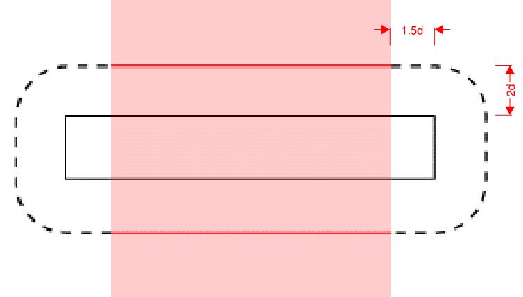
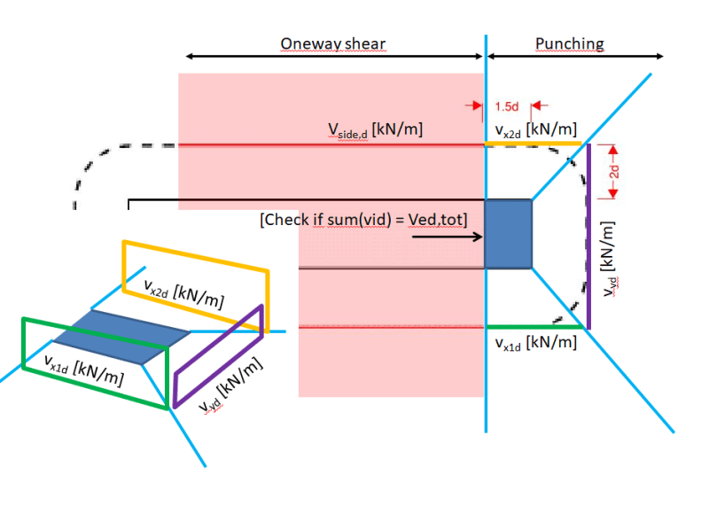
At what point should you start deducting the shear going through the red hatch zone from the total punching shear (which will be assessed using the dashed shear perimeter)? It would be overly conservative to assume the total punching demand is going to be concentrated at the corners of a 2500mm x 300mm blade column.

From a purist point of view, I think you should then check each end of dashed shear perimeter separately as there may be one end receiving much more shear than the other. I know this is all heading towards the whole "...the slab will need to unzip to punch argument..."

punchingggg_riawc4.jpg
 
Replies continue below

Recommended for you

For a straight punching shear failure check, I don't think it would matter what the aspect ratio is. The failure perimeter is what it is.

For an eccentric loading, the length along the sides that could be included is beyond my understanding to theorize about. I'm guessing it would be at least somewhat dependent on the amount of reinforcing, both longitudinal and transverse, in the slab. If I had to come up something, I probably would go no farther than the thickness of the slab down the sides past the end of the shaft.

 
Sorry - clarification on the extent of the dashed shear perimeter. Eurocode has the following limits. "d" = average depth of tension steel in slab.

punchingggg2_wbpdj6.jpg
 
WARose,

Are you saying one-way shear on the dashed semi-circle perimeter?

Yes. Or the red line. There would be a variety of checks. One thing I would check is the two way punching shear with the increase in shear stress due to the moment (transfer) in the slab at that 3 sided corner.
 
I would have thought KootK would have passed through by now. Does anybody know of any recent research into this issue?

 
Consider how it could fail.

I think it could either fail by punching over its entire area (less likely as you go further and further beyond an aspect ratio of 4) - or - the slab itself could fail in one way shear if the slab “thinks” the blade column is a wall. In this case however you need to then check normal slab shear in addition to wall end punching.
 
Trenno said:
I would have thought KootK would have passed through by now. Does anybody know of any recent research into this issue?

Oh, I've passed through plenty. As you can imagine, this is something that interests me a great deal. Unfortunately, I'm still not done noodling. And may never be. I've always had a problem with this that makes it pretty terrible. Consider slab curvature as you pass from being not on the wall to being on the wall. It pretty quickly has to go from max curvature to zero curvature. That rapid deceleration in moment implies a an almost infinite amount of shear and something akin to prying action at the ends of the walls that would exacerbate the punching stress at the ends and all but neuter the validity of any one way shear checks etc in my opinion. At least any checks that one might be doing using hand-generated load take downs.

And then, with prying in play, there're questions about what this looks like for, say, a roof slab versus a situation with wall above and below. Lastly, I would think that the situation would vary a great deal with the ratio of slab thickness to wall length. A wildly thick slab would have little prying and the conventional checks would be valid. A relatively thin slab, which is most of them, would have a ton of prying and I would think the conventional checks would be crap. And, of course, the code checks on this are not indexed to reflect slab depth to wall length ratio. So there's that.

For what it's worth, my strong suspicion is that the code provisions were developed intending that the wall ends would be taking the load that comes into the wall outside of the wall ends. Of course, proving that statement and reconciling it with my intuition is another matter.

So far, my "solution" has been to take the total load coming to the wall and to design integrity steel near the wall ends to deal with all of that. All integrity bars perpendicular to the wall. This way, even if I never sort it out, at least nobody will be pancaking a floor slab on my watch. Plus it sort of looks right on a rebar plan somehow. I put more stock in that than one might think.

 
CEB-FIP Model code clause 7.3.5.2 uses only the end 1.5dv at each end of the wall as the control perimeter. The rest is ignored.

 
Tenno said:
At what point should you start deducting the shear going through the red hatch zone
You should be ok with 1.5d as postulated in EC or modelcode 2010.

However for "long columns" or wall ends/corners we check the area of the red line like normal one-way shear along a common wall and the ends separately for punching.
The wall-ends we split up in sectors as below, so you don't have the check the whole shearforce Vd [kN] of the column or wall-end against some mixed up punching resistance. Instead use the code formulas for punching without multiplying the length of the critical section to check the shear in each sector at each wallend [in kN/m]. You can get the actions out of a FEM but be careful since the shear output is (depending on the mesh, program etc.) sometimes very approximate. Always check the reactions of the wall-end against the sum of the shear in the critical section (load transfer in the slab over the wall or numeric issues...).

Do not use Vu/Ac+Mu/J (in ACI) or the beta (in EC) to determine the max shear in the critical section. As the given example could be a bridge pillar, the vx1 and vx2 would be much larger (in the direction of the main span) than vy. The shear forces in the critical section would not be as the code formulas of punching may imply (derived from the column/wall-end reactions).

This way, you can provide the amount of shear reinforcement in each section and direction if necessary. Or at least you have a better tool the look at it in some special cases. Or get some ideas how to approach it, i wont say its the way to do it.
For new constructions I almost always put in some minimal shear reinforcement (stirrups or dowels) to provide ductility and the ability of stress redistribution. Or at least some integrity steel as KootK mentioned.

There are some "sophisticated" models which take into account thick or thin slabs i.e. the slab rotation and also the grain size and med/mrd as well. Search for critical shear crack theory, this one is documented in the modelcode 2010 and actualliy in use in the swisscodes since 2003. I’m not that big fan of it since you have to get a lot of parameters, and its sometimes not very clear how to do that. You don’t get the sector-model as described above in the code but there are some papers around (like "Non-axis-symmetrical punching shear around internal columns of RC slabs without transverse reinforcement", Muttoni 2011) where they look at x and y directions separately. That’s why I came across Trenno’s question.
At least it’s interesting how the different codes (ACI, EC, SIA) approach the punching problem when they are otherwise often very similar.

punch1_aa6fl4.png
 
Taking this to an example.

250thk C32/40 slab. Columns are 2000x250(x3m) on 5m x 10m grid with 2m cantilevers. Live load 5 kPa. Mesh 0.5m. Left hand side modelled with single node columns and right hand side with multi-node walls.

ps_mesh_upplel.jpg


ULS Shear Stress (X)
ps_shear_x_cshot0.jpg


ULS Shear Stress (Y)
ps_shear_y_ice1wu.jpg


One-way (red hatch zone) strips according to EC2.
ps_strips_n3m3kz.jpg


For the "column" model the shear going across Design Strip #3 is 145 kN. For the "wall" model the shear going across Design Strip #7 is 25 kN.

Obviously, shear is concentrating at the wall ends and therefore it would seem more correct to have these columns modelled as walls to get a more accurate shear distribution around the shear perimeter.
 
In a normal blade column and short wall I would assume all of the load comes in on the ends.Nor oneway shear into the sides. There will be moment shear carrying the load into the side back to the ends.

I think Model code defines a blade with dimensions greater than 4:1 as a wall.

Swiss code goes further and appears to say for any column, only the corner 1.5d contributes, even for a square column.
 
Status
Not open for further replies.
Back
Top