Eng-Tips is the largest engineering community on the Internet

Intelligent Work Forums for Engineering Professionals

Bollards - ICYC 12

Status
Not open for further replies.
Replies continue below

Recommended for you

Very nice, dik. This question comes up a few times a year around here, so I'm glad somebody has consolidated it into a nice article.
 
Packard should have extended it to include for the design of the foundation.

Rather than think climate change and the corona virus as science, think of it as the wrath of God. Feel any better?

-Dik
 
I couldn't find a CIDECT DG 10... not out yet?

Rather than think climate change and the corona virus as science, think of it as the wrath of God. Feel any better?

-Dik
 
What I find truly interesting is when people try to justify the bollard design of a standard pipe bollard being hit by a heavy fork truck that doesn’t have a bumper to absorb the collusion shock energy. No one wants to talk real numbers. They continue to say it has always worked so no need to look into it. Even though I hear that fork trucks easily destroying these standard bollards and don’t provide must protection. Which I find interesting because I don’t see engineered bollards like the “slow-stop” bollard specified on that many manufacturing or industrial projects.
 
I must be living in a different world than the authors of this article. We provide 6" or 8" bollards that are routinely hit by forktrucks in industrial plants. For the most part, damage is minimal and consists of chipped paint and a few dents. For anything more substantial than that, bollards are sacrificial and replaced (and the forktruck driver is drug tested and put through training). Design bollards for a force of 60k?.....huh?? What slab on grade, elevated slab (like the one in the car park mentioned in the article), or bollard foundation can take that? Its worth mentioning that the actual force seen by a bollard decreases dramatically when there is any movement of the bollard (such as deflection imposed by the impact force). Also note that the 60k force is WAY more than the force noted in IBC usually taken at 18" (I think) above the surface. Sorry guys, this article misses the mark.
 
Can anyone give me a bit of a hint about where this comes from? I guess it's part of the AISC...

Clipboard01_yyvuih.jpg


I get a Mr = about 50 K_ft 81 K_ft (wrong fy). with a Zx = about 21 in^3. I'll post my SMath program when it's finished... I'm not sure how it misses the mark... I haven't finished the program yet to check output... I've always used 'light', 'medium' and 'heavy' bollards based on experience from damaged ones. I've not used energy for checking. I don't know how this 'shakes out' but Packard is well known in HSS design.

Rather than think climate change and the corona virus as science, think of it as the wrath of God. Feel any better?

-Dik
 
MotorCity,

Well you are in the majority with respect to not paying much consideration to bollard design. But let me ask you this, have you ran the numbers yourself?

Personally, I have heard a second hand story of workers almost being killed because a fork lift truck a bollard and easily struck down the bollard. These weren’t my designs but this gave me pause and opened a door for me to look into it further.

I was shocked just like you with some wildly high numbers. Take a look at another article below and consider the forces with respect to a fork truck that weighs a lot and doesn’t have a shock absorbing bumper. Also keep in mind the bollard doesn’t deflect as much as you need it to do so either.


Finally without getting into some long winded discussion: check out this website for a bollard company that has solved this problem and has engineering to back it. Are they wrong? One thing to note too is they solve your concern with respect to high loads by absorbing the energy.


Also if you dig into IBC or ASCE you realize the load is based on passenger vehicles too. Personally I feel like the article hits the mark.
 
The design speed in the article is 20 mph which is well beyond the intent of a safety bollard. Even in a factory in which forklifts are zipping around, 20 mph seems an unsafe speed for a forklift. At that speed, the slightest turn of the steering wheel would be catastrophic. The article also assumed fully fixed condition which would require a rather large section of foundation. I think most bollards are embedded in soil which would have an real spring value, allow some rotation and reduce the demand.
 
Pvchabot,

A few things of note. When I was running my calculations I was running them at 5-10 mph with a rigid 3-ton fork truck and was trying to simulate two bollard designs. One where it was embedded 3’-6” below grade in concrete and another one bolted to a concrete mat. I modeled them in STAAD with springs to try and get the most movement as possible (even softened a few springs). Even then it wasn’t deflecting enough to cut down the loads to a reasonable number. In my opinion, traditional bollards only make sense on paper for vehicles with frames meant to compress like a bumper (crush distance). I would be very interested if someone could make a standard bollard work with a 3 ton fork truck.
 
Standard bollards work by taking damage (bollard and vehicle). Trying to get energy absorption in the elastic range doesn't stack up (as DayRooster says). An image search for "damaged bollard" shows this.

20mph head-on is getting into anti-terror range. Not quite, but serious impact. The Australian code goes from 30kN for general car park areas to 240kN at the bottom of a ramp. It goes up real quick with any speed.
 
Does the Australian code use the noted force at a point of impact... like 0.5m above grade? and doesn't use an impact calculation?

Rather than think climate change and the corona virus as science, think of it as the wrath of God. Feel any better?

-Dik
 
0.5m above ground for the loads I posted (light traffic). There's also a 40kN at 1.0m for medium traffic, but no ramp load given for that case.

They're based on 2m/s and 0.1m stopping distance, and 6m/s and 0.15m for the ramp case.
 
Thanks...

Rather than think climate change and the corona virus as science, think of it as the wrath of God. Feel any better?

-Dik


I looked to the article published by STI , ( and prepared by By J. A. Packer )... I am familiar with EUROCODES and looked again the Eurocode 1 Part 1.7.. Apparently , the article has been prepared with a HYBRID approach ( Loads from EC, Plastic design of HSS Bollard with AISC....) Probably the mass of vehicles (Zhao et al ??? 2019) from web search..

My gut feel is something wrong with this calculation and MotorCity (Structural) has a valid point (and a big PS for that)..

My arguments are.

- The subject formula ( F = v √km ) is at Annex C Dynamic design for impact (which is Informative , not normative )
- Table 4.1 Indicative equivalent static design forces due to vehicular impact of the code ( Normative ) proposes for Courtyards and parking garages with access to: for cars Fdx= 50 kN Fdy = 25kN
- Table 4.2. Indicative equivalent static design forces due to impact on superstructures for Courtyards and parking garages 75 kN
- 4.4. Accidental actions caused by forklift trucks , F = 5W ( if we assume 4 tons ) F= 5*4= 20 tons and say 200 kN still less than 270 kN.
- The proposed vehicle mass ( large SUV ) is WEIGHT of the vehicle .. The mass would be m= W/g = 300 kg mass ( assume g=10.0 m/sec^2

- In this case the force would be F= 9 * SQRT (300,000*300) = 85000 N= 85 kN ( say 20 kips)


If we look the dimensional analysis of the formula ;

F = v √km We should use the ( F,L, T ) dimensions .. V= L/T , k= F/L m= ( F* T^2/L)

In this case ( assume the letters in parenthesis F= ( L/T) *SQRT *((F/L)*( F* T^2/L) so, F= F and mass in the formula will be kg-mass ( not kg- force )

P.S. If you get the info . free of charge from web, i always consider that , WORLD WILD WEB .. (Say , my thoughts..) and I will suggest to get a copy of Eurocode 1 — Actions on structures —Part 1-7: General actions — Accidental actions together with National Annex ( NA+A1:2014 to BS EN 1991-1-7:2006+A1:2014 )

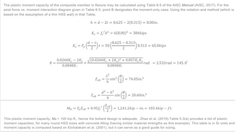
 
There isn't an error in the vehicle mass, which is 3000kg (3 tonnes) - equivalent to 30kN weight. This is a massive energy to be absorbed. In the calculation, it's assumed that the vehicle crushes 0.9m (3'), and has average 4.6g deceleration.

I looked up SlowStop bollards on youtube. They don't have anything like this impact. About 20% of the energy is where they stop.

A lot of vehicle bollards are intended as warning markers. Driver realises they hit something and stop, before they hit something important/someone. Stopping a vehicle that isn't being stopped by the driver (terrorism, medical etc) is different and big.
 
It would make sense to me to design the baseplate to yield as the energy absorbing mechanism. The anchors have to be beefy with sufficient embedment to make that work, but it’s a rational approach.
 
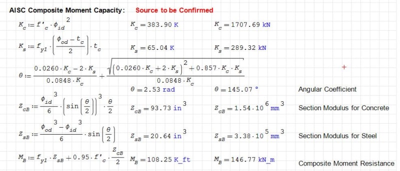
I thought it was a neat article. Dimension units are consistent. It appears that the approach is using Working Stress Design. I've put together a SMath program for it and it appears to be at least dimensionally OK. Does anyone know the source for the formulae presented in the article as I noted above. I've also looked at the Canadian CSA S16 composite flexural strength using our LRFD and the bollard 'fails'; I've got to re-check the numbers before I post it.

Clipboard01_to8r3f.jpg


Rather than think climate change and the corona virus as science, think of it as the wrath of God. Feel any better?

-Dik
 
Steve - I am with you on this one. Energy absorption is difficult to achieve. These crush distances are sometimes wild numbers to achieve reasonable loads. For reference those slow stop bollards are designed for heavy fork trucks hits but at modest speeds. But these are only solutions for a very specific bollard market (manufacturing or industrial). Even then those highly engineered bollards can’t take anti-ram loads at high speeds. In my opinion, the anti-ram bollards is a special design that is either a giant monolith of concrete or a field tested vendor supplied bollard.

Bones - I am interested about the energy absorption of a traditional baseplate. In theory that is what the slow stop bollard does at its core. It is a special baseplate that has an engineered amount of energy absorption. So I can wrap my head around the idea of a special designed baseplate that would function as a energy dissipation device. I guess my question is what does that calculation look like for a standard base plate? How much energy would be absorbed in a hit before the baseplate shears or tears?
 
Status
Not open for further replies.
Back
Top