Continue to Site

Eng-Tips is the largest engineering community on the Internet

Intelligent Work Forums for Engineering Professionals

  • Congratulations KootK on being selected by the Eng-Tips community for having the most helpful posts in the forums last week. Way to Go!

Bolted Joint Prying Stresses of the Clamped Member

Status
Not open for further replies.

1980c3

Mechanical
Mar 11, 2022
19
Howdy folks,

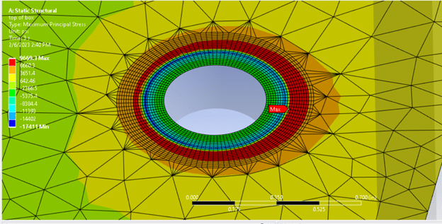
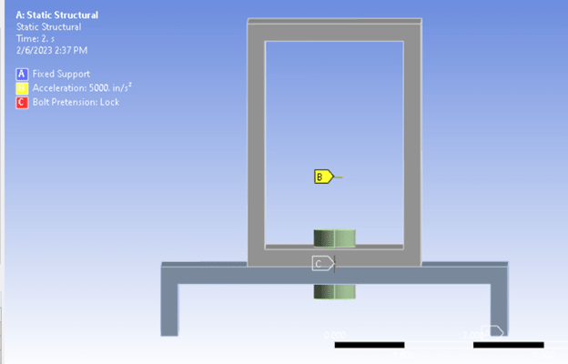
In my FEA, I am encountering a scenario in which the bolted-on assembly is experiencing lateral load due to vibrations (should be a screenshot). As the top box tips over, the bolt head essentially "digs in" on one side and pries at clamped material. The peak principal stresses are found near the edge of the bolt's contact. Would you expect this to be singular? In changing the density of the inflation region around the bolt hole, it for sure does NOT seem strongly mesh dependent (meaning I change the mesh and the results change by 5% at the most). Thoughts?


The bolt to plate contacts are all frictional. And, for clarity sake, I am dedicating a time step to applying the bolt clamp, and locking the bolt for the remaining steps.
Picture2_ln2xtv.png


Picture1_qmgj6y.png
 
Replies continue below

Recommended for you

Would you expect this to be singular? > Yes.
Thoughts? > Modelling a bolted joint at this level of detail is a futile exercise in wasting a lot of time and beating one's head against a solid wall. There are all sorts of tolerances, clamp-up, friction, etc. effects and non-linearities that are not modelled and probably can't be modelled. Just test the thing.
 
"thoughts" ?

1) don't use FEA on a bolt/hole. There are perfectly good allowables published.
2) Never expect to get "truth" from a linear model (as I assume you're running).
3) if vibrations are causing your bolt head to "dig in", then the problem is with your assembly or your assumptions. I'll assume (again) that this head digging in is something you've seen in practice, and not just a FEA prediction. If the former, and you can't add additional bolts to increase the lateral stability of your assembly, then increase the preload on the bolt, or stiffen the base of the assembly (thick washer plates). If the latter, I'd look into how your modelling assumptions are causing this (how are the various pieces restrained).

"Hoffen wir mal, dass alles gut geht !"
General Paulus, Nov 1942, outside Stalingrad after the launch of Operation Uranus.
 
Thanks folks. Its certainly NOT something we have a lot of practice with (modelling bolted joints to an.... acceptable?..... accuracy.) We have a lot of history taking FE assemblies and extracting the force and moment reactions to gather an estimate on the fatigue life of bolts. Not so much on the "clamped" members side.
Do you folks have any publishings related to the clamped members' localized stresses (thus fatigue life)?

That's really all I am after!

EDIT: to the point of testing, it's a bit tough. This is going to be in a application where high cycle fatigue is present. So its a bit tough to just test....
 
well, to be fair, you never mentioned it was a fatigue problem.

Again, is this a real problem, witnessed in real life, or an FEA "phantom" ?

If you're saying you loading your structure and get prying under the head, then I'd say thick steel washers should "help" and more preload (to clamp your assembly to the baseplate).

If you really are worried about the bolt head digging in, then probably there is very little literature for this (other than short notes saying "don't do this"). I reckon the stress state is horribly triaxial, and you're talking about the wear of different materials, etc ...

"Hoffen wir mal, dass alles gut geht !"
General Paulus, Nov 1942, outside Stalingrad after the launch of Operation Uranus.
 
Sorry for my ambiguity... certainly this is a FEA "phantom" at the moment, however I could see a case where a fatigue crack could initiate in the indicated regions.

And yep. it is big time messy on the stress state side.

I do like the idea of thicker/bigger washers underneath the bolts of interest. I will certainly pursue that.
 
I second the use of big thick washers. And install the fastener with high torque (clamp up).

And if the critical loading is vibration, then put it on a shaker table and test it.
 
@desertfox,

Thanks for the document. Unfortunately that seems focused on the fatigue of the bolt instead of the clamped material.

 
Hi 1980c3

Sorry I thought it was the bolt fatigue you were after, that said whenever I have looked at bolt joint fatigue it’s only the bolt I’ve considered similar to your experience. I will have a dig around and see what I can find.

“Do not worry about your problems with mathematics, I assure you mine are far greater.” Albert Einstein
 
No problem. and same here. This is truly the first time I have considered the clamped member... to a certain degree, maybe that should tell me something.
 
It's the head digging in that I'd worry about.

Is a load of 400g real ? Is it real as a static load (that's how I read your pic) ?

"Hoffen wir mal, dass alles gut geht !"
General Paulus, Nov 1942, outside Stalingrad after the launch of Operation Uranus.
 
Hi rb1957,

The load is not really realistic... truthfully this model is a simplified model to replicate a problem encountered in a separate, much larger model. I just scaled it down to a model that was easier to show and explain.
 
so there is a real problem, or just an FE problem, with the larger model ?

You're running Linear FE ?

"Hoffen wir mal, dass alles gut geht !"
General Paulus, Nov 1942, outside Stalingrad after the launch of Operation Uranus.
 
Just an FE problem at the moment, and yes, linear materials (frictional contacts of course).
 
Hi 1980c3

I have been thinking (yep that’s dangerous for me) about the bolt hole and why would you have a fatigue problem under the nut, surely all the stress is compressive in that region and if my understanding is correct fatigue stresses only grow under tensile stress. I appreciate that you can get tensile stress in two bolted components due to bending etc but these surely wouldn’t be under the nut at the bolt hole. I suppose tensile stresses can occur under the nut but I think for that to happen the bolt preload would have to be insufficient when the joint was made.
Not saying I am right but just thinking about it.

“Do not worry about your problems with mathematics, I assure you mine are far greater.” Albert Einstein
 
the fastener shear does create a tension stress, and this can be a fatigue problem. But I wouldn't use a linear FEM to predict stresses near a stress concentration.

"Hoffen wir mal, dass alles gut geht !"
General Paulus, Nov 1942, outside Stalingrad after the launch of Operation Uranus.
 
Hi rb1957

The fastener shear might well create a tension stress but is that in the clamped pieces or the fastener itself.

“Do not worry about your problems with mathematics, I assure you mine are far greater.” Albert Einstein
 
Hi folks, for what it's worth, the linear FEM stresses are intended to be corrected for plasticity using Neuber's rule (and eventually strain levels used in strain life assessments). And truthfully, since the FEM is reporting a positive principal stress, there is certainly a direction that is experiencing tensile stresses. It might be more worthwhile to create a solution combination and plotting essentially the dynamic stresses... as opposed to the principal stress plot of the bolt clamp's residual stress and the stress from the box attempting to tilt.
 
Hi 1980c3

Sorry I can’t find anything to help you with the clamped parts and fatigue, everything points to the bolt itself.
I have retired from engineering so I don’t have access to any stress computer programs😀.

In all my working life I have seen bolts fail in fatigue but never the clamped parts, with all due respect are you certain the fea you have is correct?

“Do not worry about your problems with mathematics, I assure you mine are far greater.” Albert Einstein
 
Status
Not open for further replies.

Part and Inventory Search

Sponsor