Eng-Tips is the largest engineering community on the Internet

Intelligent Work Forums for Engineering Professionals

  • Congratulations waross on being selected by the Tek-Tips community for having the most helpful posts in the forums last week. Way to Go!

Bonding/Adhesion of 2 wooden beams. 1

Status
Not open for further replies.

Floyd44

Structural
Aug 23, 2019
10
0
0
SI
Hello there,


For a long time, there has been something in my mind, which i cant seem to figure out how to deal with it.

By the way, this is totally a hypothetical question:

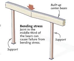
How do you calculate stiffness/Strength of 2 wooden beams bonded in the middle, but they are joint longitudinal, kind of like the scheme bellow. The joint is straight out FLAT, so no cuts or grooves. Also the beams are simply suported on both ends.
______________ _____________
......Beam nr, 1 ||Beam nr. 2
_____________||_____________

I wanna calculate deflection of the said beam. If you were to lineary press it in the middle (where the joint is)
If it was a normal beam i would take formula δmax = 5 q L4 / (384 E I), but here i dont know how to do it, if it is even possible.

Which parameters are important here? Obviously type of adhesive and the type of material used for the beams, and tensile strength, is there anything else that would need to be taken into the account?

Best regards,

 
Replies continue below

Recommended for you

the formula is for uniformly distributed load and not for "linearly press in the middle"
PS : ... even with the best performing glue I would never do it !
 
Yeah, sory i made a mistake, i meant uniformal load.

Of course you wouldnt do that, but does anybody know how to calculate the deflection of such a joint?
 
You mean like this?
BeamSplicedMidspan_gnhxth.jpg


You would need super glue (not currently available). Alternatively, you would provide scabs on each side glued and bolted to each beam.

The spliced beam, if you did it properly, would be pretty close to a normal beam, so deflections would be calculated as if the beam were continuous. For a point load in the middle, D = PL[sup]3[/sup]/48EI where D is deflection and P is point load.


BA
 
Yeah like this,

Okay i know its a bad design and all. I just want to know if it is possible to calculate the deflection of such beam - glued in the middle, for a normal glue.

How would you add, the adhesion and area of the glue into the formula.


For as long as the glue holds, a concentrated angle change φ would occur at the splice due to strain in the glue. The angle change at each support would be φ/2. Deflection due to glue strain alone would be φL/4 where L is the span. Total deflection would be: PL[sup]3[/sup]/48EI + φL/4 for a concentrated load P at midspan.

The magnitude of φ would depend on the properties of the glue used. As soon as the glue started to tear, the beam would collapse instantaneously.

Note that φ must be expressed in radians for the above to hold.

BA
 
I'll throw it out there that most glues used in glulam production, work on the principle of the glue being stronger than the parent wood. i.e. the joints are tested to ensure that the failure occurs in the parent wood, not though the glue joint.

Most glulam joints however are staggered in each lamination and the individual laminations are finger joint with a 'zig zag' cut, not direct end glued like is being theorised here. I suspect this is a bad idea.

So as such I'd suspect you're asking the wrong question, you should be asking at what stress/deflection does the glue start to creep (or contribute to deflection) or flat out fail in this type of application, and you really really want to avoid that occurring as it's not recoverable and failure of the glued interface probably isn't far behind if it does hang on to start to contribute to deflection.

As an aside don't do what you are proposing in practice, it's just a bad idea alright. At the very least the finger jointing should follow the local relevant standard, most likely this requires the use of a zig zag type cut, and testing of the joints to ensure the parent wood is the failure mechanism (effectively taking the glue out of the equation if you like).
 
@BAretired, can you really take into the account that the ''E'' of the glue is the same as of the wood?


@Agent666, i think the point of ''zig-zag'' cut is to increase the area of glue on the same section.
And thats what im trying to figure out, how much does the area and strenght of glue effect the deflection formula and how.


You can also use FEA to include adhesive’s strength in the simulation. This is done with so called cohesive elements. Such model can be very accurate when you include correct damage initiation and evolution properties for adhesive layer.
 
Floyd44 said:
@BAretired, can you really take into the account that the ''E'' of the glue is the same as of the wood?

Definitely not!! The magnitude of the concentrated angle change at the splice depends on the properties of the glue, not the properties of the wood.

Floyd44 said:
@Agent666, i think the point of ''zig-zag'' cut is to increase the area of glue on the same section.
And thats what im trying to figure out, how much does the area and strenght of glue effect the deflection formula and how.

For the kind of splice you are talking about, the area of glue is the same as the area of the beam and the length of glue is nearly zero. It is an abutted connection where one beam butts up against the other with virtually zero space between.

Apart from balsa wood model airplanes which I built in my youth, I have not seen glue used structurally in tension. Usually, it is used in shear as in glulam beams or plywood gusset plates.

I'm not sure why you are pressing this issue. As others have indicated, the concept of a glued butt splice is not recommended, and certainly not at the point of maximum moment.

BA
 
Status
Not open for further replies.
Back
Top