Eng-Tips is the largest engineering community on the Internet

Intelligent Work Forums for Engineering Professionals

Bottom Flange Bracing - Providing bracing past beam splice

Status
Not open for further replies.

EngDM

Structural
Aug 10, 2021
367
1
16
CA
Hey all,

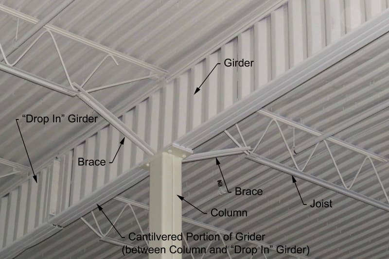
I was wondering what the general consensus is when providing bottom flange bracing for a cantilever beam, but providing the bracing past the beam splice within the drop-in section. For instance, we have a 5'-0" cantilever, but joists are at 6'-0" on center. I can use a bottom chord extension at the column to brace the bottom flange there, but my next joist is past the beam splice. Does bracing past the beam splice do anything for the cantilevered beam? Or is the unbraced length for negative bending just the cantilever distance to the splice since that is where moment goes to zero (non moment connected splices).

Aside, yes there will be negative moment on the non-spliced span, but assumed that that is taken care of with bottom flange bracing in this case.
 
Replies continue below

Recommended for you

EngDM said:
Does bracing past the beam splice do anything for the cantilevered beam?

Much depends on the details but I feel as though one could plausibly claim that, if the first joist in braces the drop in beam torsionally, then that would do a pretty good job of also bracing the tip of the cantilever beam torsionally. You're not going to introduce much flexibility as a result of torsion in that last 1' of drop in beam. And even a shear plate connection at the end of the cantilever would probably do a decent job of torsionally bracing that so long as the depth of the connection is > 60% of the depth of the cantilever.
 
I feel there a case to be made that the splice connection likely could provide enough torsional load transfer to brace the cantilever beam end using a brace on the drop in span 1 foot away.

An alternative would be to provide an angle triangle brace similar to those when your column doesn't align with a joist.
 
I'd like to see a detail where that bottom chord bracing to the bottom of the open web steel joist actually works. What I usually see in the field is spaghetti with no deliberate load path. The brace is usually L2x2x1/8", far beyond any l/r of 200 (I suppose you could argue it as tension only, but if this is as critical a connection as it seems to be, the weld and alignment of these elements is borderline fantasy). Anyway the brace is something similarly "stick" like, and in my mind it will buckle under a forty pound load. If you brace both sides you can create continuity that's unwanted, and then you need a compression/tension brace load path worked out if it's on a single side.

Bracing to the top chord has much more lateral restraint (for the top chord), unless you're planning on using the bottom chord bridging element to brace the bottom chord, which is decidedly NOT what the bridging is there for.

Hemstad, Michael (1999). "Cantilever Beam Framing Systems," Engineering Journal, American Institute of Steel Construction, Vol. 36, pp. 129-137, see note 8.


Funky_brace_cunznh.jpg


Note the lack of bottom chord bridging at the first bottom chord panel point "not uplift" detail.

Brace should be in quotations here. It's a "brace" until it's loaded. Then the bottom chord goes into compression and immediately buckles. Whatever weld is there isn't going to offer meaningful torsional restraint when the bottom chord starts to buckle.

This may be common design practice, but it's not based on a calculation and an established load path, if you ask me.

More discussion here,
 
Hi lexpatrie.

It seems like you have something insightful to say there however I'm currently quite confused on what your point. Some of the nomenclature you have used here seems to have gone straight over my head. Would you mind elaborating? Possibly with more diagrams?

Using the secondary members to brace the bottom chord of the primarily roof members is common practice where I'm from. But we'd call them beams or roof rafter and the secondary members purlins. The braces themselves are fly braces and can be designed for tension only or compression/tension depending on the whims of the engineer.
 
I did a system like this recently. I found that the cantilever girder needed its bottom flange braced to prevent bucking in the wind uplift condition, so I used bottom chord extensions for the joists at the columns and one set of joists into the span (not the cantilevered end). The joists had to carry moment due to the induced continuity, but I thought it gave me a nice solid load path for both bracing the top of the column and the bottom flange of the girder.

We were involved in a PEMB failure where those little diagonal braces were too small and too long (and too few) to properly brace the deep PEMB girder and several bays just rolled over. Loads were not close to max design loads. Nasty stuff. Ours was a little different than yours in that the bottom chord was extended part way and the little brace workpoint was at the end of the brace not at the first bottom chord/web workpoint.
 
All of the OWSJ manufacturer's I've dealt with prefer the brace to go to the top flange panel point. Since the top chord is already sized for compression, it often doesn't change the size of the joist chord, but since the bottom flange isn't designed (at least in my area) for much compression besides wind uplift (in my area it's not that onerous), the beam bracing loads often result in an increased bottom chord member.
 
If it were a simply supported span, that Steel Design after College discusses a Cb of 2.0. Steel Design after College Handout Slides 45-49. That same document has a fair bit of material on cantilever beams, as well.

When you have goofy framing like this the Cb gets a lot murkier and it's a separate issue from the brace "design".

What I'm getting at, is in the picture above, regarding the brace, it doesn't look to me like there's much restraint at the joist bottom chord to brace connection, so any thrust would tend to produce buckling.

My comment about "uplift" bridging is usually when there is net uplift that is properly specified is customarily on the first bottom panel point (It's not there in the picture above). There's also no "tie joist" (stabilizer plate for the bottom chord of the joist and an joist bottom chord extension that is NOT welded together) at the column, but anyway.

Joist_girder_-stabilizer_plate_dygyoj.jpg


That photo shows a stabilizer plate for the joist girder (the lower one, a vertical plate), and it's kind of showing a "seat" for the joist coming in from the left, rather than a true stabilizer plate.

Back to the comment on uplift bridging being missing -

..Per SJI SPEC:
A single line of bottom chord bridging must be provided
near the first bottom chord panel points whenever uplift
due to wind forces is a design consideration"

(Bridging - How it works and what to work around, Brotherson, Holtermann, Steel Joist Institute, August 15, 2018, slide 29)

Cantilever Roof Framing Using Rolled Beams, AISC, year unknown, circa 1994.
 
Status
Not open for further replies.
Back
Top