Hello fellow Engineer,
Our office is asked to evaluate an existing roof framing structure that was modified previously due to the addition of a higher roof. Please see attached photos below.
You will notice that, in order to handle the new drifting snow load, the following modifications were done:
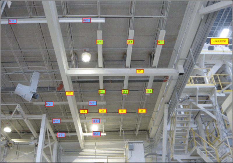
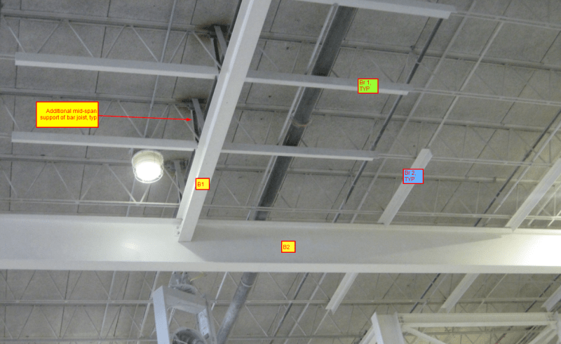
• Introduce an additional support to the original steel bar joist (at mid-span)
• Reinforce the bottom chord of the original roof joist with steel angle “Br 1”. Braces “Br 1” are not attached to Beam “B1” ” (There is a 1” space between the end of brace “Br 1” and the top flange of beam “B1”)
• Introduce a WF beam “B1” to pick up the reactions from the new support of the roof joist.
• Introduce a WF beam “B2” to support (1) end of beam “B1” and support the other end of beam “B1” on a hanger connected to a braced frame.
• Introduce steel angle “Br 2” (welded to the bottom chord of the roof joists) to brace beam “B2” along its span. However, the steel angles “Br 2” are not attached to Beam “B2” (There is a 1” space between the end of brace “Br 2” and the top flange of beam “B2”)
Engineers in our office agree with the followings:
1. Capacity of the roof deck (Fiber board roof deck) needs to be checked for drifting snow.
2. Top chord of roof joist (at new support of roof joist) needs to be checked for bending.
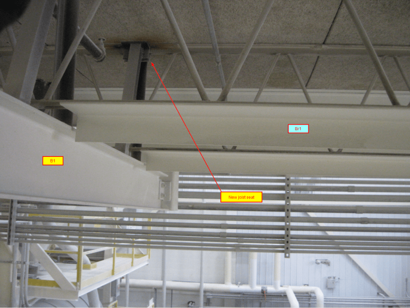
3. Capacity of the new joist seat needs to be evaluated.
4. Stress reversal of web members of the bar joist needs to be evaluated.
5. Check capacity of beam “B1” and “B2” to support reactions from new bar joist seat.
6. Check the strength and stiffness of brace “Br1” and, especially, brace “Br2”
Finding information to work on #1 (Allowable capacity and as-built thickness of the fiber roof deck) and #6 (out-off plane stiffness of steel bar joist) are some of the challenges for us. However, the #5 is the one that has caused some debates and discussion among us.
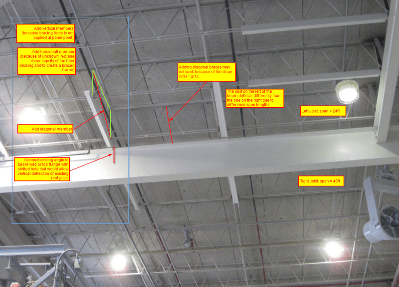
One side argues that it is because the steel angles are not attached to the top flange of the beams, they (steel angles “Br1” and “Br2”) are not bracing the beam at all per AISC Steel Manual
The other side argues that if beam “B1” and “B2” buckle laterally, the top flange of the beam would be in contact with the vertical leg of the steel angle. Hence, the beams are being braced. This is engineer’s judgment
Would you consider that the beams “B1” & “B2” are being laterally braced by “Br 1” & Br 2” respectively?
Do you have any information on the fiber roof decking (Building circa 1965’s)? I am guessing that the fiber roof deck will not be able to handle the additional drifting snow of 60 psf (on top of the balanced/ flat roof snow load of 35 psf), what you do?
 Thank you!
Our office is asked to evaluate an existing roof framing structure that was modified previously due to the addition of a higher roof. Please see attached photos below.
You will notice that, in order to handle the new drifting snow load, the following modifications were done:
• Introduce an additional support to the original steel bar joist (at mid-span)
• Reinforce the bottom chord of the original roof joist with steel angle “Br 1”. Braces “Br 1” are not attached to Beam “B1” ” (There is a 1” space between the end of brace “Br 1” and the top flange of beam “B1”)
• Introduce a WF beam “B1” to pick up the reactions from the new support of the roof joist.
• Introduce a WF beam “B2” to support (1) end of beam “B1” and support the other end of beam “B1” on a hanger connected to a braced frame.
• Introduce steel angle “Br 2” (welded to the bottom chord of the roof joists) to brace beam “B2” along its span. However, the steel angles “Br 2” are not attached to Beam “B2” (There is a 1” space between the end of brace “Br 2” and the top flange of beam “B2”)
Engineers in our office agree with the followings:
1. Capacity of the roof deck (Fiber board roof deck) needs to be checked for drifting snow.
2. Top chord of roof joist (at new support of roof joist) needs to be checked for bending.
3. Capacity of the new joist seat needs to be evaluated.
4. Stress reversal of web members of the bar joist needs to be evaluated.
5. Check capacity of beam “B1” and “B2” to support reactions from new bar joist seat.
6. Check the strength and stiffness of brace “Br1” and, especially, brace “Br2”
Finding information to work on #1 (Allowable capacity and as-built thickness of the fiber roof deck) and #6 (out-off plane stiffness of steel bar joist) are some of the challenges for us. However, the #5 is the one that has caused some debates and discussion among us.
One side argues that it is because the steel angles are not attached to the top flange of the beams, they (steel angles “Br1” and “Br2”) are not bracing the beam at all per AISC Steel Manual
The other side argues that if beam “B1” and “B2” buckle laterally, the top flange of the beam would be in contact with the vertical leg of the steel angle. Hence, the beams are being braced. This is engineer’s judgment
Would you consider that the beams “B1” & “B2” are being laterally braced by “Br 1” & Br 2” respectively?
Do you have any information on the fiber roof decking (Building circa 1965’s)? I am guessing that the fiber roof deck will not be able to handle the additional drifting snow of 60 psf (on top of the balanced/ flat roof snow load of 35 psf), what you do?