Continue to Site

Eng-Tips is the largest engineering community on the Internet

Intelligent Work Forums for Engineering Professionals

  • Congratulations MintJulep on being selected by the Eng-Tips community for having the most helpful posts in the forums last week. Way to Go!

Breaker Failure Timing

Status
Not open for further replies.

timm33333

Electrical
Apr 14, 2012
198
I have a question about the breaker failure relay. The breaker failure total clearing time is calculated in the chart in Figure 3.8.3 of NERC presentation (as attached.)

There is some time (about 1 cycle ) for 50-operate/50BF, then some time (about 10 cycles) for 62BF, and then extra time (about 0.5 cycle) for 86BF. So when the relay has both 50-operate/50BF and 86BF combined in the same relay, then shall we still need to include the extra time for 86BF?

Also in this diagram, what does the transfer trip time mean? Thanks for help!
 
 https://files.engineering.com/getfile.aspx?folder=eeb1b59d-a511-40a4-99ad-24fd7a587d67&file=Breaker_Failure_Timing.PNG
Replies continue below

Recommended for you

Not necessary to include 86BF time separately when the function is part of 50BF relay. The transfer trip time is always applicable and relates to the relay at the remote end that will be energised by the local end 50BF to route the trip command to the remote backup breaker.
Remote backup breaker could be
- all those breakers connected to the same busbar in case of 50BF tripping the concerned bus.
- the breakers at the remote end of transmission line or
- the breaker on secondary side of power transformer.
 
Thanks. A few questions. What is the typical fault clearing time of breaker, should we use 5 cycles for local breaker and 3 cycles for the remote breaker?

Figure 3.8.3 (attached above) of NERC document indicates that the total breaker failure clearing time should coordinate with the transient stability study of the plant. For example if the transient stability study determines that the maximum critical clearing time to maintain transient stability is 10 cycles, then the total breaker failure clearing time should be less than 10 cycles. But in case we don’t have the transient stability study done for the plant, can we ignore this requirement of coordinating “total breaker failure clearing time” with the “maximum critical time required to maintain the transient stability”?

I think it would be better to use the upstream transformer secondary breaker as the remote breaker (instead of using all the breakers together connected to the bus as the remote breaker), is it correct?
 
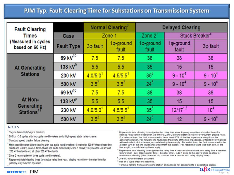
Typically, for any breaker regardless of where it is in the system, 5 cycles is a common assumption for 3 cycle breakers and 3.5 cycles for 2 cycle breakers.


I've had EEs tell me a 3 cycle breaker should always trip under 3 cycles and a 2 cycle under two... but reality has sad otherwise.


You should always have a transient stability. Always.


If the transient stability is less then the BF timing you have to weigh your options. Set low or risk high... I know of applications where BF has been set less than 10 cycles at large nuclear power plants.

Typically where transient stability becomes an issue IPO (independent pole operation) breakers are deployed. The reasoning is that a single phase fault has a higher stability and critical clearing time than a 3 phase fault. If a 3 phase fault does occur it is not likely that all 3 poles would fail simultaneously. Only one. So as such a 3 phase fault would quickly turn into a single phase fault and the stuck pole can be delayed accordingly without concern.

 
You might like this report, see page 31 of 132:


I remember a while back reading a really good detailed explanation of how the BF relaying was set at a Florida nuclear plant possessing abnormally low critical clearing time. The logic was biased/based on the load conditions or something to that effect... really wish I could find it. Then again it might be way more than you would need to worry about.

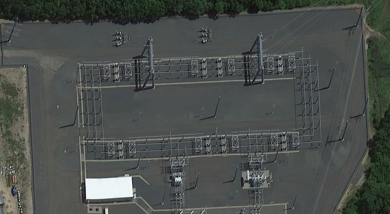
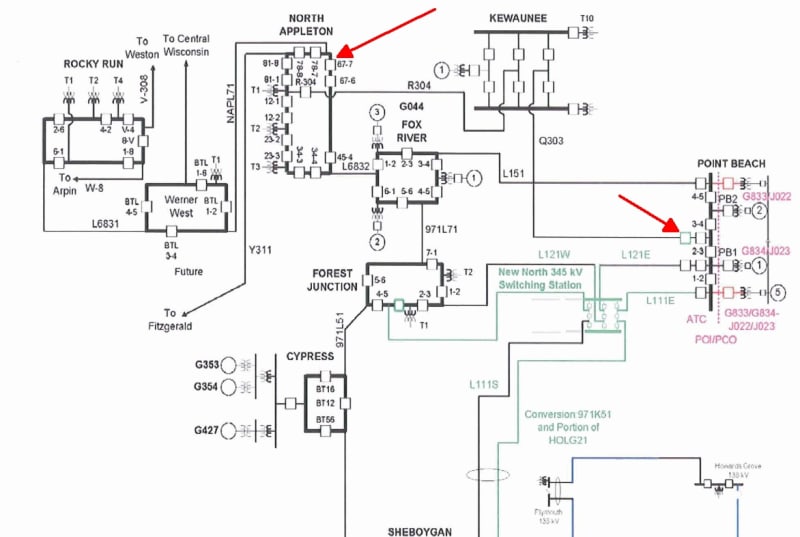
FWIW, I have even heard of engineers placing breakers in series. While not necessarily the reason in the following examples, I decided to include them if you ever need the inspiration lol. ;)


breakers_in_series_1_t7fs43.jpg


breakers_in_series_2_gjue43.jpg
 
If you can imagine that the Q303 series breaker was installed during a complete rebuild of the 345kV single bus at POB. Apparently that was easier than converting the existing single bus to something more flexible. The first time I saw L121 with the existing series breaker, I could not for the life of me understand what purpose it was serving.
 
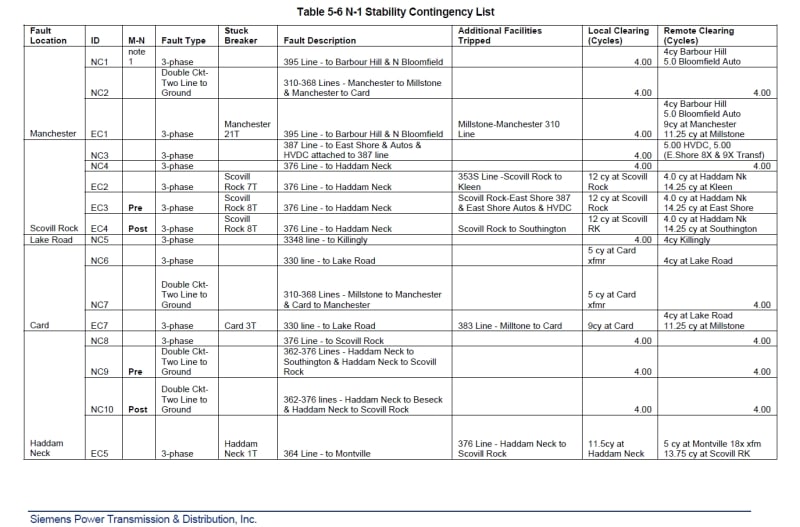
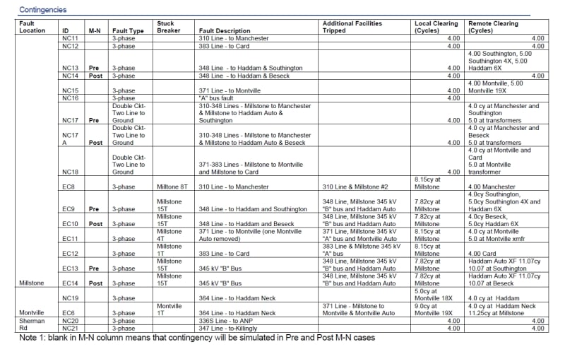
At Millstone, even if the primary breaker trip time (7.82 ms) is larger than the secondary breaker trip time (4 ms), still the total clearing time (11.82 ms) would be less than the critical clearing time of transient stability study, so it should be Ok.
 
In our case the same relay has 50, 51, and 50/62BF functions. As 50/62BF is not an overcurrent relay, so relay coordination study is not applicable for it. However still we have to perform the settings of 50/62BF which in this case would be the fault clearing times of breaker failure.

For relay coordination, we calculate the overcurrent settings (50, 51) by software and then export to excel sheet, and from excel sheet we export the settings into the relay.

How shall we transfer the settings of 50/62BF into relay? Can we calculate the settings of 50/62BF (fault clearing time of breaker failure) in excel and then export from excel into the relay? Thanks
 
@thermonic1: Yup- a lot of times series breakers are used where a stuck breaker produces unacceptable results by clearing two or more elements. Its not just existing straight bus installations but also new breaker and a half substations where clearing the neighboring circuit for a stuck center breaker violates thermal or voltage criteria. Buss and neighboring element outages coordinated at load or generation dispatch where both elements out is not a concern.

breakers_in_series_1_nuydvb.jpg


@tim3333: Not milli seconds, but cycles on a 60Hz system. Meaning 1 cycle is 1/60th of a second.

For 50BF, you can set that quite low, below the lowest current value that will pickup anything in the relay since it will only activate after the breaker has been called to trip. Meaning if 50BF stops seeing current after 3 cycles it stops timing, if it keeps seeing current it keeps timing until it hits you BF setting time and action takes place there after.


If you want to make it more secure you can use AND logic with your 52A position switch but I personally would not do it. For lines I would simply use over current BF, for transformers I am tempted to use OR logic- meaning current or 52A thats not opening. Transformers with no load on the secondary may not pull enough current to pickup 50BF meaning a stuck breaker can sit feeding a transformer indefinitely.

Personally, (personally, meaning its always different for others) I'd rather have breaker failure inadvertently operate for a normal fault then fail to operate during a fault with an actual stuck breakers. For a false BF initiation you will typically clear only one other element, maybe none maybe a few. For a BF that will not trigger when need you can easily clear the entire station usually leading to some very severe consequences.
 
Status
Not open for further replies.

Part and Inventory Search

Sponsor