Continue to Site

Eng-Tips is the largest engineering community on the Internet

Intelligent Work Forums for Engineering Professionals

  • Congratulations IDS on being selected by the Eng-Tips community for having the most helpful posts in the forums last week. Way to Go!

Bridge Anti-Falling Device 3

Status
Not open for further replies.

Anselbray

Civil/Environmental
Mar 1, 2020
1
IMG20200211121844_ivlwiz.jpg
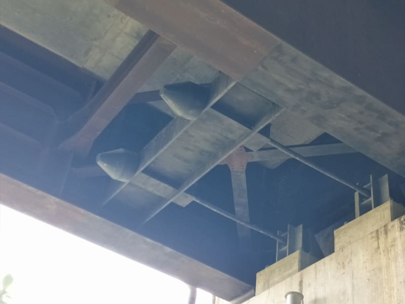
I was working on a bridge repair project and I happened to encounter this so-called "bridge anti-falling device" item along with the scope of works. Can anyone help me with how this works or what are the components of this? My initial assessment is that this was only a post-tensioned cable.
Thank you.
 
Replies continue below

Recommended for you

Among other things there could this be a site where the bridge might be subjected to strong flood flows tending to dislodge it? Looks like a great idea to limit the longitudinal expansion and especially shrinkage tending to be excessive at times.
 
Just guessing, but it looks like some type of seismic damping device to me. The box-shaped sleeves on the left end of those high strength bars is likely house some type of viscous damper.

Rod Smith, P.E., The artist formerly known as HotRod10
 
They look more like some sort of post tension structure. The doodads on the right anchor to the abutment, while the left side cranks the bed against the abutment.

TTFN (ta ta for now)
I can do absolutely anything. I'm an expert! faq731-376 forum1529 Entire Forum list
 
I had a similar thought initially, IRstuff, but pulling the bottom of the girders towards the abutment under most circumstances would reduce the load carrying capacity of the bridge. Even if it were an odd situation where it did enhance the capacity, given its location and size, the effect would be minor; not much 'bang for the buck'.

Rod Smith, P.E., The artist formerly known as HotRod10
 
I'm curious as to where it was referred to as an "anti-falling device". It could be a bearing restraint (something to keep the bridge girders from coming off of their bearing seats), which I suppose could, somewhat non-technically, be referred to in that way.


Rod Smith, P.E., The artist formerly known as HotRod10
 
I guess the bearing is a roller that has excessive lateral movement that require some significant works unless it is restrained, but not rigidly that would prevent expansion. This could be a hydraulic jack type setup.
 
BridgeSmith, I was thinking more that the roadway structure is somehow floating on the supports, and the anchors keep the roadway structure from slipping off the supports. Not sure why anyone would build it that way, but who knows?

TTFN (ta ta for now)
I can do absolutely anything. I'm an expert! faq731-376 forum1529 Entire Forum list
 
IRstuff said:
I was thinking more that the roadway structure is somehow floating on the supports, and the anchors keep the roadway structure from slipping off the supports.

Sorry, I misunderstood what you were saying. That is a possibility, but it seems unlikely to me. There are several common ways of providing the type of restraint you're describing, but that wouldn't be one of them.

Rod Smith, P.E., The artist formerly known as HotRod10
 
Note the square box on one side of the "tie to beam", and the bullet on the other side, the two pieces could for a closed cylinder. Also, the slightly bend rod (on the far side), indicating compression.
 
Bridge deck falling-off Prevention Device during seismic event. This could be steel cable or articulated steel rod with piston. I found the picture below at web...
falling_off_prevention_device_vdcmyo.png
 
I can say with 95% certainty that those are seismic cable restrainers. Our office has designed about a dozen of these for various bridges around my state.

The thing that gives me pause is that the bridge does not look that old, and yet these are typically installed on older bridges. They are used because the older bridges never considered the ramifications of seismic displacement. Based on your seismic analysis, if any of the following are true, the bridge could be a good candidate for cable restrainers:

1. Bridge bearings are not sufficient to resist the expected levels of displacement and bearing failure is a possibility.
2. Girder seat length is not long enough and your girder could potentially fall off the seat
3. At expansion piers, out of phase superstructure movement is excessive enough to cause large openings at deck joints and you want to limit their relative movement away from each other.

I am not 100% certain what the bulbous caps on the end are, but my guess is that they are either grease caps or anti-tampering caps. The ones that we have designed use a bearing nut and a jamb nut. The bearing nut is not fit snug to the face of the beam since we need to allow for a small amount of serviceable movement for every-day use. For seismic events, where the movement is higher, the nut will engage.

Further observations, from where I come from, that is one strange bridge design..... Lateral bracing at the top and bottom and only at the end bay!? Mid-height, short diaphragms with varying flange width..... (3) Intermediate added flanges along the web!?
 
Lateral bracing at the top and bottom and only at the end bay!?

With full-depth cross-frames, lateral bracing top and bottom is typically unnecessary, but with the shallow diaphragm, the top and bottom flanges may have both needed bracing. Sometimes, the unbraced length only needs to be shortened a little. It may also be possible the lateral bracing is part whatever load-resisting system the rest of those components are for.

Intermediate added flanges along the web!?

Those would typically be called longitudinal stiffeners. It's rare to see even one on bridge girders anymore, much less 3 of them. It's generally more cost-effective to use a thicker web, nowadays. We even try to avoid transverse (vertical) stiffeners, unless we can reduce the thickness of the web on a long girder by adding just a few.


Rod Smith, P.E., The artist formerly known as HotRod10
 
Thanks Rod. I completely spaced on the terminology for the longitudinal stiffeners. I've never used them and remember reading exactly what you mentioned... that they are just not economical and cost more than the benefit that they add. Seems that the OP is from the Phillipines so their standard of practice must be different.
 
OP is from the Phillipines so their standard of practice must be different.

Yep. It's all in that labor cost to material cost ratio. In the US, it used to be material was expensive and labor was relatively cheap, so you'd see bridge girders with 5/16" webs, with a longitudinal stiffener on one side of the web, and vertical stiffeners every 3' or so on the other. Today, the ratio tilts toward labor (especially certified welders) being much more expensive, so now we do 1/2" or 5/8" webs with no stiffeners (except the connection plates for crossframes or diaphragms and bearing stiffeners). In some areas of the world, the steel is still expensive, and even welders will work for low wages.

Rod Smith, P.E., The artist formerly known as HotRod10
 
Status
Not open for further replies.

Part and Inventory Search

Sponsor