Eng-Tips is the largest engineering community on the Internet

Intelligent Work Forums for Engineering Professionals

Bridge Connections

Status
Not open for further replies.

Usman Tanveer

Civil/Environmental
Sep 16, 2022
13
0
0
PK
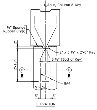
Greetings . So, the thing is I want to design a hinge/pin connection between deck and abutment. The tricky part is both of them are concrete sections. There are many guides available for steel connection or even steel-concrete sections but for designing concrete-concrete connections the guide always talk about giving lap lengths or anchorage lengths that is, a fix connection. I read a comment here where someone was talking about analyzing with a hinge connection but giving a fix connection in real life and everyone was endorsing it citing accidental moments. What if I don't want my abutment to experience those moments.
Is there a guide for pin/hinge connection design for two concrete sections in bridges?
 
Replies continue below

Recommended for you

Concrete hinges in new bridge construction have been abandoned long time now. Main reason is defects, high maintenance requirements.

What you are describing as "hinge design - fixed construction" is coming down to how you detail reinfrocement (no anchorage), in many peoples mind. Not in mine though.

The whole idea of concrete hinges is to create a weak section, which releases the moment but doesn't fail. That's what a Freyssinet hinge is: Link

Citing: The use of concrete hinges in new design is not permitted, unless there is absolutely no alternative
solution, such as in situations where the articulation of an existing the bridge being widened has to be
maintained. In such cases, the hinges are required to be designed to be accessible for inspection and
maintenance CD 350 [Ref 8.N].


Doesn't a rocker bearing between bridge and abutment (behaving as a hinge) suffice?
 
Thankyou for your time kostast88. As far as my definition of a hinge is concerned it is same as you described that is, releases moments and transfer forces. I have attached a picture which in my mind is a hinge/pin connection where the development length requirements are not met(hence no fix connection). In the picture two concrete members are just simply joined together. I am looking for that design.
Furthermore rocker bearing may suffice. Can you share some manual explaining its design against lateral and vertical loading?
 
 https://files.engineering.com/getfile.aspx?folder=c14559d6-75e9-4ee9-ade6-be88b74564ed&file=WhatsApp_Image_2022-09-28_at_4.48.45_PM.jpeg
The system in the photo doesnt look do-able. These are dowels/anchors that resist shear.
You have 80mm gap for expasnsion. But the anchors will prevent any movement and will take the full shear. Depending on your spans, this could be huge. The end block will be loaded only on vertical forces,as is in your photo.

Is the contractor trying to avoid buying bearings? I don't see why you don't provide them here.
 
The typical solution for a concrete box girder (and steel girders where the thermal expansion is too large for a fully integral abutment) is what called a semi-integral abutment, where the end diaphragm is rigidly connected to the deck and girders, and the whole thing rests on a steel-reinforced elastomeric bearing supported by a cap.

In the rare instance where the abutment foundation can accommodate rotation but not translation, we typically use a fully integral abutment that's hinged below the abutment, like this:

hinged_abut_xwhv3o.png


Rod Smith, P.E., The artist formerly known as HotRod10
 
Greetings BridgeSmith, Yes I am looking for a fully integral abutment hinged below the abutment. Can you tell me where can I find a good design of it?
 
Each design will be different, based on the substructure type and restraint conditions.

Our most common fully integral abutment type has steel H-piles embedded into cap, with the end diaphragm rigidly connected to the cap and the girders, which is not freely hinging abutment, but we do assume the piles form a plastic hinge under the cap. We design the cap to diaphragm connection for the plastic moment capacity of the piles to ensure that happens.

If we need free rotation and translation, we typically provide steel-reinforced elastomeric bearing pads to support the girders and accommodate translation and rotation. The design of the elastomeric pads from the AASHTO LRFD specs is fairly straightforward, although it typically takes some iteration to get to the most efficient sized pad that meets all the parameters.

Rod Smith, P.E., The artist formerly known as HotRod10
 
The_State_of_the_Art_of_Precast_Integral_Bridges.pdf find on line

Go to nydot and find bridge manual, should have drawings and design requirements
 
Greetings BridgeSmith, I have provided an elastomeric pad and it take care of all things you mentioned .However in a curved bridge on some of pads ,I am experiencing uplift, small in magnitude but it is there, As elastomeric pads are flexible in translational direction and not longitudinal one this posses some challenge .Is there any waly I provide an elastomeric pad while also taking care of all uplifts in pads in curved bridge.
 
You will need to provide uplift restraint apart from the elastomeric pads - they don't survive well with the elastomer in tension.

Providing translational movement capability and uplift restraint at the bearing location woud probably require some type of sliding bearing system, rather than an elastomeric. Where we have superstructure uplift, we either use a fully integral abutment on steel piles (often embedded in a concrete caisson, with 15' of unembedded pile at the top to allow for the pile to flex, providing tranlational freedom) and/or provide counterweights (concrete blocks between the girders).

Rod Smith, P.E., The artist formerly known as HotRod10
 
I have attached those pictures which are causing me confusion in this regard. On one hand the engineer has provided a bearing pad to allow some translational movement, while on the other hand he has provided he has provided an anchor to do the bidding against uplift thus making bearing pad useless in this regard. And from your earlier comment, we cannot provide steel piles(economy). However if you can provide some guidelines or code or solved example for the uplift restrain while allowing lateral movement(for Sliding bearing system, Fully integral abutment on steel piles or counterweights) maybe we can make something of it. Thankyou
 
 https://files.engineering.com/getfile.aspx?folder=05e0319d-b596-486a-a1b2-94d233f90f29&file=WhatsApp_Image_2022-12-31_at_10.14.58.jpeg
I know I've seen sliding bearings with guides and PTFE sliding surfaces, but I don't think we've used one anytime recently.

Depending on how much counterweight is needed, it could be as simple as expanding the length of the end diaphragm and filling in the end of the box girders.

I don't have any details of the pile/drilled shaft combo at the moment, but what we've done typically consists of piles partially embedded in a drilled shaft. For instance, a 38' 12x53 H-pile, with shear studs on the web for the bottom 20', set 35' into a 30" diameter drilled hole. Then the bottom 20' gets a reinforcing cage and poured concrete. The pile is embedded 3' into a concrete cap with alternating holes for reinforcing bars reinforcing bars through the web and shear studs. The girders are clamped down to the cap using cast-in u-bolts. We tried straight threaded rods, but the contractor 'forgot' to cast them in, and did their typically poor job of cleaning the holes and mixing the epoxy for the epoxy anchors, and they popped out, creating a huge headache for everyone, so now we give them u-bolts.

Rod Smith, P.E., The artist formerly known as HotRod10
 
Status
Not open for further replies.
Back
Top