Continue to Site

Eng-Tips is the largest engineering community on the Internet

Intelligent Work Forums for Engineering Professionals

  • Congratulations IDS on being selected by the Eng-Tips community for having the most helpful posts in the forums last week. Way to Go!

Bridge Deck options for 15'X35' vehicle bridge

Status
Not open for further replies.

larrym

Marine/Ocean
Oct 8, 2002
27
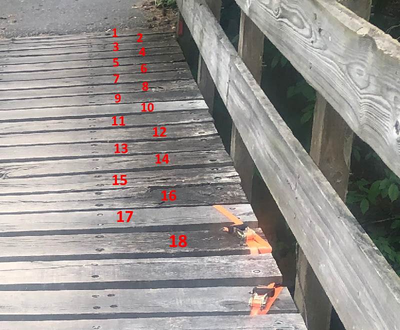
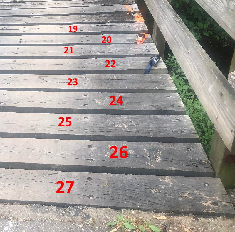
We have a privately own/maintained bridge that is 15'W X 35'L. With Concrete abutments, 4-5 steel I beams spanning between the abutments and wooden decking (4X10s??).

We are working with a structural engineer and looking for a crew to do needed maintenance on the bridge. I am looking to understand what the options are so I can converse with the engineer, etc. from at least a basic understanding...

This bridge is the only access for about 8 residential houses. There are several emergency access/egress points that might be used...but normal access is only via the bridge.

The wooden bridge deck is in need of replacing and someone has suggested to the home owners assoc. that owns the bridge that we could do a concrete deck without a problem...

Anyone have any references I can access from the web, etc. Or even a library if needed. I realize this area of engineering (Art/Science) has be around since before my Grandfather was around...but it's not an area that I have done any design work. I understand the physics... more looking for things like how the bridge deck beams are secured since they can move around as the environment changes from summer to winter, etc. Also how to maintain the wooden deck beams for maximum life...

Larry

Larry Mackey
 
Replies continue below

Recommended for you

A concrete deck will weigh a good bit more than the wood deck and forming/placement of the concrete will be more difficult. The weight might be more troublesome (for the beams) and I would expect the cost to be higher (maybe a lot). Don't know if the durability of concrete would be much better than wood. That all might depend on your climate (think: de-icing salts).

I am a fan of the wood decking and specify it "all the time".

4-5 "I" beams is a vague term (I understand you're not as familiar with this area of engineering). Usually I see "wide flange" beams (inside faces of flanges are flat not sloped). Simplest way to differentiate the beams is depth, width and flange thickness. They are designated as "W" shapes. Age of the beam is a factor too as steel strengths are much better in recent decades and private bridge beams are often older/salvaged material. All of that might not be a problem but, just something to be aware of when performing design checks. Look out for abutment scour protection too.

Anyway, at 4 or 5 beams over the 15 ft width, that should be maybe about 4 feet spacing so decking is spanning not too far and I would assume the 3.5" is vertical for the planks. I usually find 4x6 are more readily available in pressure treated lumber (Southern Pine in Eastern states Doug Fir in Western states). The steel must be well painted or hot dip galvanized for corrosion protection, either way (concrete or PT lumber) but PT is especially corrosive to steel. Usually it is nice to place a layer of wood decking on top of the planks to provide surface wear protection. Also looks a little "cleaner". Here's a pic of one I did recently.

Concrete deck might be possible but I would not expect it to be a better fit for cost/vs durability
 
 https://files.engineering.com/getfile.aspx?folder=b611eceb-c246-462b-874d-6c07abf95ec2&file=Photo_Sep_15,_11_00_25_AM.jpg
Larry,

A properly constructed and maintained bridge deck can last 75 to 100 years; 8 1/2" thick; use high performance concrete, epoxy coated or galvanized rebar; no black bars; after the deck has cured apply a penetrating sealer, preferably silane or siloxane. If you're in the US, check your state DOT web site for their bridge deck specification and details; and they probably have price information.

With that said, you have to consider constructability. As you stated "There are several emergency access/egress points that might be used"; your bridge will probably be out of service for about a month. at 15' wide it's too narrow to do in stages. The demo, forming, and placement will take about a week; then you need about two days to set up the finishing machine; a day to place the concrete; and 14 days of wet cure. It will be expensive; the contractor will probably have to pump the concrete or use a crane and bucket, unless you discharge at both ends; at least it's only two truck loads.

Another thought, you could construct concrete panels at the site. Make them 5' x 15'; you would need 7 to go across the length of the bridge. The panels would weigh about 7,500 #, which can easily be picked up with a large back hoe. Leave pockets in the panels to install stud shear connectors; use high strength grout in the haunches, stud pockets, and joints between the panels and you're done; probably in a week tops.

Another option would be to use steel plates as your deck then pave it with asphalt. I wouldn't go that route. It would require a lot of overhead welding, which is expensive and you'll be repaving every 5 to 10 years.

Timber's not bad for a lightly travelled bridge. I have to go through my files later to see what I have or your state DOT may have some details.

Take look at life cycle costs for the various schemes. You may want to consider replacing the bridge with a prefabricated or precast system. Check the Contech website for ideas Link. They have a lot of ideas; they even have a feature that allows you do a trial design (No, I don't work for them.)
 
Greatly appreciate responses. Picture of bridge deck attached. 5 steel beams spanning between abutments. Bolts in deck boards are attaching to wood laid on top of beams (I assume but have not seen clips holding those boards onto steel beams. Many of bolts holding down the deck boards have sheared. (which is what the straps are meant to address ;-))

The Concrete curing process, etc. was something the (home owner's) Bridge Committee did not hear (or was not told) from the engineering group that they had been talking to... Which was my concern... the bridge being down for even a few days would require extraordinary planning, permissions, costs etc.

Thanks on the reminders of the scouring at the base of the abutments....Duh!! (I do shore landings for international submarine cables for a living so....scouring is something I should remember ;-)

Thanks for the suggestion on the state DOT...thought had not crossed my mind...I had to go back a few years on the engineering manuals to find timber as a bridge material ;-)

Current Rating on the bridge is posted as 27 Tons (I have not yet seen the engineering report that was based on which "supposedly" said actual was higher).

Traffic on this bridge basically consists of home owner vehicles (<50 crossings a day) plus daily trips by UPS, USPS, Fedex and other occasional delivery services and a once a week trash truck (they use one of their lighter trucks).

Since my house is literally "Over the River and through the woods" ;-) and we are patiently waiting for grandkids ;-) we want this bridge to be around for a while!!

Regards
Larry


Larry Mackey
 
 https://files.engineering.com/getfile.aspx?folder=5fccc0df-225c-4bd2-9f64-86c50ae4a74c&file=IMG_1410.JPG
Larry - Have you field measured bridge dimensions and counted the beams? Things are not adding up.

1) There are 27 deck boards in the photo (counted them several times). If they are 4x10s, even with at 2" gap, span will be less than 30 ft.

2) There are 7 longitudinal lines of bolts. If there are 5 beams, what are the other 2 bolt lines for?

Before making any serious plans or talking to the engineer, suggest field verifying bridge dimensions, position (spacing) of the beams, height and flange width of the beams, dimensions of deck boards / gap. Get the clear span of the bridge (face to face measurement between abutments), not just the length of the deck.
The details will make a huge difference in what approach to repairs is practical.

[idea]
 
Can you provide a photo of the understructure of the bridge and the abutments?


A Great Place For Engineers to Help Engineers

Follow me there.....
 
15’x35’ field measured. Apologies on limber size. I can’t count and am Not used to lumber this size ;-)
I’ll measure the boards and get some underneath pictures tomorrow

Regards
Larry

Larry Mackey
 
Larry,

Below is a link to NYSDOT timber bridge details. They're for an all glu-lam structure. However, the deck and railing details can be modified to fit your need.

Link

Attached is a NYSDOT report on timber deck bridges; has some good details for connecting timber deck to steel beams.
 
 https://files.engineering.com/getfile.aspx?folder=2236dba4-599d-4e16-a50a-14607dee076c&file=2013_LBC_session_3-3.pdf
I had trouble counting, too, but finally confirmed 27 deck boards:

BridgeDeck-18-800_x4vkkt.jpg


BridgeDeck-27-800_t2bdry.jpg


For the bridge deck to be 35' long, deck boards have to be about 15 1/2" center to center. Assuming a 2" gap, each board is about 13 1/2" wide... I doubt it.

Even though the deck has been measured before, measure it again. Get the other measurements I suggested also. Even if I am totally wrong, without accurate as-built information your entire effort is being wasted.

[idea]
 
At a superficial glance that bridge looks pretty good and decent condition!
 
My concern with these is the underlying steel.
If it shows signs of corrosion it needs to be cleaned and examined.
Then likely it will need to be re-coated. A good blast job, a zinc rich primer, and the correct top sealer coating.
Where the deck is in contact with the steel is an area to focus on.

= = = = = = = = = = = = = = = = = = = =
P.E. Metallurgy, Plymouth Tube
 
The load rating of 27 tons is fairly good, assuming that's either the inventory or operating rating (not so good if that's a nominal/permit load rating, without load factors applied), and it's for one of the rating trucks configured with a single rear axle (H-15, H-20, Type 3), as opposed to those with multiple rear axles (HS-20, Type 3-3).

Was the deck load rated also, or was it just for the girders? If the deck wasn't rated, it will need to be analyzed using the actual girder spacing, thickness and width of the planks.

Our typical rehabilitation of a bridge like this would likely be to add runners and call it a day.

 
OK, after figuring out that I can't count or measure....and apologizing to my long since passed (master carpenter) Grandfather for not measuring twice, etc. etc....apologies for that

The Bridge deck dimensions are 25ft X 12ft.
27 each deck boards (2 1/2" X 9" 12ft long) spacing between deck boards varies from 1 to 3 inch seem to average at ~2.5in
5 each steel I beams 8 inch flange X 10 inch height (was not able to get a good flange thickness or web thickness).
Yes they need to be scrapped, and/or sandblasted inspected and repainted.
In addition to the I beams the outer beam on either side of the bridge is a C channel 10 inch high and 3 inch flange

On top of each of the seven (7) beams is a 3"x6" board that the deckboards are lag bolted into.

So I am assuming rehabbing this bridge is about a week (or longer) job consisting of:
1. Clearing off all the existing lumber
2. Clean, inspect and repaint the steel beams
3. Replace and secure the boards on top of the beams
4. Replace and secure the deckboards

What are the pluses/minues of adding runner boards on top of the deck boards?? I kinda understand their purpose but with the limited traffic this bridge sees are the runners adding much benefit versus cost??

The sign at the bridge says 27 tons. I have not yet seen an engineering report/etc. that supports that number.

All the rain lately has brought the creek up several feet so I was only able to get limited pictures today. The attached was as close as I could get underneath without getting wet...


Larry Mackey
 
 https://files.engineering.com/getfile.aspx?folder=d7e06ba0-9f77-4ef1-871f-d9802c1fbc49&file=file-39.jpeg
The runners help distribute the load to multiple deck boards, which helps with the wheel loads that the deck can carry, and also helps a little with distributing of the load to the girders.

I thought you had an actual load rating in hand. A posted sign doesn't mean much if you don't know who put it up or how long ago, especially if there has been any significant section loss to the girders.
 

Section loss on the girders should be fairly obvious (in the way of rust).
Usually I find the rust is greatest where the beams are bearing on the abutments. Often depends on how the end dams are done and how much soil is piled up against them.

I don't think the runners do much to distribute load unless they are very thick (which is unusual). I have spec'd them mostly as a wearing surface to protect the planks.

FWIW - I don't think much of that guardrail anchorage...
You might consider running a plank out long and having a 4x4 (or similar kicker) come up to improve the bracing of the guardrail posts. Just a thought.

 
larrym said:
Many of bolts holding down the deck boards have sheared.

This is most likely because deck boards (2 1/2" x 9") are too "thin" and the beams (W10 with 8" flange) are overloaded.
The wood deck is flexing as traffic passes over it. Also, the steel beams are deflecting excessively.
There are, and have been for over 70 years, only three sizes of W10 with 8" flange - none of them would be considered satisfactory for a heavily loaded 25' span. Either the loads are lighter than posted or the community has been "lucky"... probably a little bit of both plus the infrequent bridge traffic and it does look like your grandfather did good construction work.

Get your engineer to evaluate both beam and deck capacity based on their current condition. The longitudinal runners (for both wearing surface and structural) that HouseBoy first suggested will help compensate for the "thin" wood deck.

If the beams have to be "upgraded" to deeper sections, costs start to skyrocket. Perhaps if the loading can be limited, the bridge can "get by" for a while.

As noted, by replace the rail and posts.

[idea]
 
Status
Not open for further replies.

Part and Inventory Search

Sponsor