Continue to Site

Eng-Tips is the largest engineering community on the Internet

Intelligent Work Forums for Engineering Professionals

  • Congratulations waross on being selected by the Eng-Tips community for having the most helpful posts in the forums last week. Way to Go!

Bridge Jacking System 2

Status
Not open for further replies.

OLDSOUL22

Structural
Oct 6, 2021
32
Hello everyone,
I am designing a jacking system to jack up a bridge for rocker replacement, I am thinking of using HSSQ 9X9 which slide in HSSQ 10X10 section as shown in the sketch, for foundation I'm using a huge steel slab with a stiffened connection to the HSSQ, for the connection to the girders I'm still between using I-Beam or a cap with a pin to allow for any girder slope. Does anyone have experience designing something similar? How would you go about idealizing the system? would you consider the connection to the girder -if welded- as a pin support and eliminate any eccentricity? would you consider any eccentricity in the other direction?
PS: Height is almost 30', FS to be 3.
Thank you!
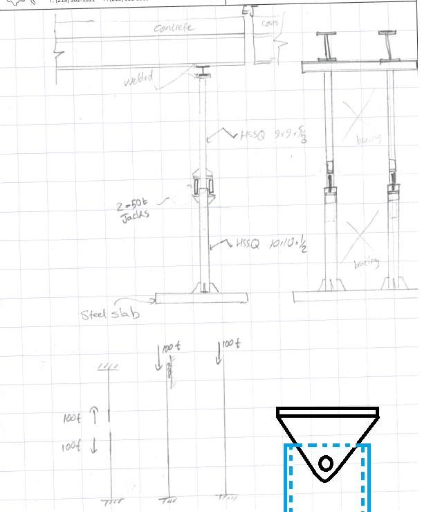
jacking_system_lb6xs0.png


Sr. Project Engineer
MSc in Civil Engineering
 
Replies continue below

Recommended for you

Typically, welding to the flanges of steel bridge girders is not allowed.

We typically require temporary bearing stiffeners in the girders at jacking locations (often 6x6 timbers each side of the web will suffice).

Even if you are allowed to weld to the girders, the girders aren't stiff enough laterally to produce a fixed end condition, so either way, it should be modeled as a pinned end.

Rod Smith, P.E., The artist formerly known as HotRod10
 
I'm not too concerned about lateral stability as ill design lateral bracing between the jacks. I'm more concerned about the direction parallel to the girders because there will be no bracing. Although, I might be able to brace the jacks to the concrete Pier somehow
Welding is not off limit around here so I guess I can accomplish a pin connection easily.
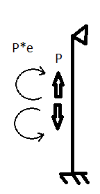
Would you agree with the FBD below? assuming no eccentricity transversely.
Untitled_tbawav.png


Sr. Project Engineer
MSc in Civil Engineering
 
OLDSOUL22 said:
I'm still between using I-Beam or a cap with a pin to allow for any girder slope. Does anyone have experience designing something similar? How would you go about idealizing the system?

As a former bridge Contractor, we never jacked beams, but have done a few other similar things as part of our means-and-methods.

IMHO, a no-brainer, use a beam not a "cap with a pin".
Keep it simple, how much will the beams be raised? A few inches?
How long are the beams being jacked? Many feet?
Therefore, what is the change in slope for the beams? Not much, I' bet.

"Slop" in the jacking system will probably make a token change in beam slope seem like "noise".


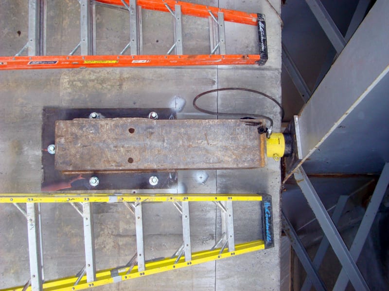
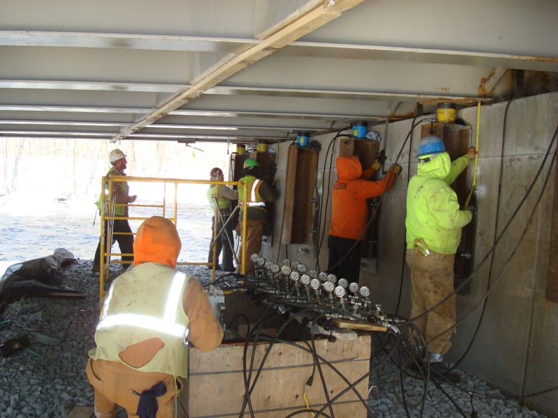
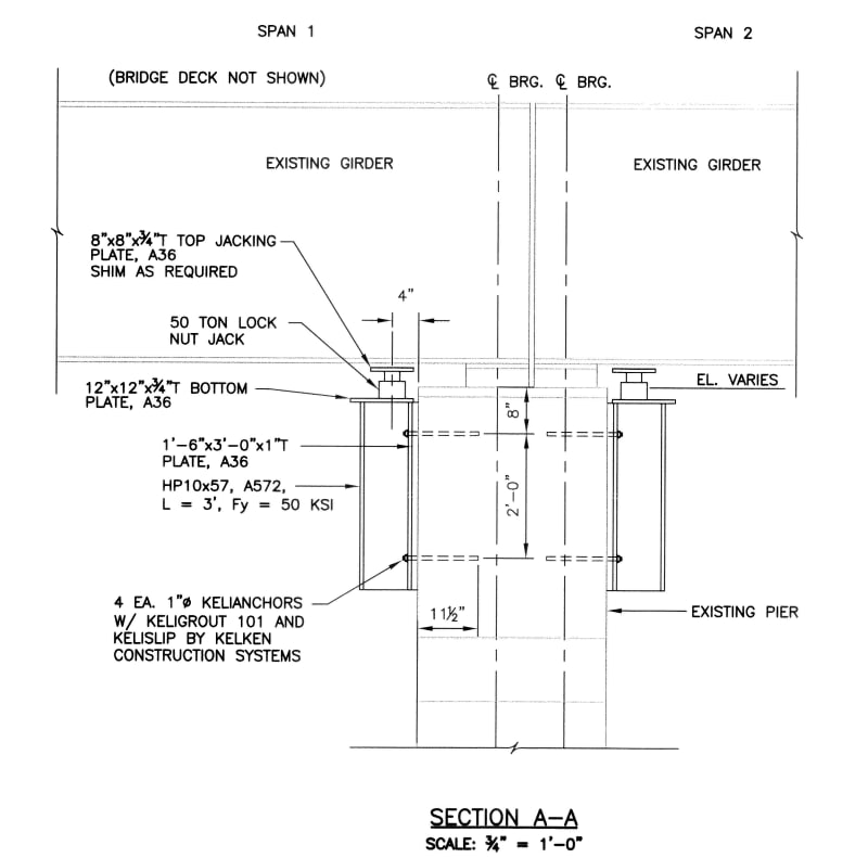
I'm not a big fan of tall, narrow posts for jacking and supporting bridge beams. I have done a number of jobs similar to the below photos. The method may vary depending on the required jacking loads.

JOB #1
DSC01463_klyxj5.jpg


JOB #1
DSC01470_zzjekb.jpg


JOB #2
Plans_NB-603_2010_09_02_PARTIAL_m8rk1x.jpg


Welding to the girders may not be expressly prohibited, but there are good reasons not to -- particularly for the tension flange of a loaded girder! I agree, get away from that detail.

Brackets to the permanent support (abutment or pier) as PEinc shows are a much better solution. This eliminates stability issues, doesn't require an expensive steel plate foundation, in many locales the brackets can even be rented.

----
just call me Lo.
 
On occasion, we've allowed (even encouraged) contractors to remove the cross frames, install temporary temporary diaphragms in their place (typically back to back channels), bolted to the bearing stiffeners (usually requires drilling extra holes in the stiffener, but we're ok with that), and jacking the girders directly from the top of the cap.

Rod Smith, P.E., The artist formerly known as HotRod10
 
Your concept seems to be a bit much with the jack in the middle. It's easier to put the jack against the beam. Attached is something from a recent project where rockers were replaced; just a column with a timber mat. I've also seen it done the way PEInc illustrated. You can also rent shoring towers and mats from Sunbelt Rentals.


[URL unfurl="true"]https://res.cloudinary.com/engineering-com/image/upload/v1658268397/tips/JACKING_DETAIL_gl9hug.pdf[/url]
 
Attached is something from a recent project where rockers were replaced; just a column with a timber mat.

That's typical of the shoring systems we see submitted for review. No reason to reinvent the wheel, and then have to fabricate it.

Rod Smith, P.E., The artist formerly known as HotRod10
 
Status
Not open for further replies.

Part and Inventory Search

Sponsor