Continue to Site

Eng-Tips is the largest engineering community on the Internet

Intelligent Work Forums for Engineering Professionals

  • Congratulations cowski on being selected by the Eng-Tips community for having the most helpful posts in the forums last week. Way to Go!

Bridge Ovhg Bracket question about hanger rod connection location.

Ron247

Structural
Jan 18, 2019
1,093
I have had several instances where I reduced the spacing for an overhang bracket because my hand calcs showed the controlling stress to occur in the cantilever of the horizontal arm from where the hanger rod connects and the joint of the horizontal to the vertical. The problem is that the load/spacing charts from most bracket suppliers indicates my reduction is excessive. My other problem is, it appears to be very simple calculation to confirm. This generally occurs when the concrete overhang is lower than the top of girder. The deeper the offset, the farther the rod moves.

I was wondering if maybe the joint of the horizonal and vertical is also supposed to move to the right with the movement of the rod connection to keep the cantilever somewhat the same. I have attached a drawing that I hope clarifies my issue. Am I missing something or incorrect about how the bracket works?
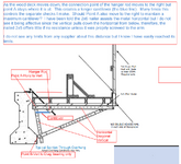
1744131622520.png
 
Replies continue below

Recommended for you

Why does the position look unstable on the top where the arm doesn’t rest against the beam?
 
Those brackets are under gravity loads. The hanger rod is the only connection at the top of the girder. It supplies X and Y reaction. The horizontal arm tries to pull away from the girder under all loads, it does not need to bear against anything. The bottom bearing connection is the only other reaction and it only supplies the complimentary X direction reaction to create the "couple" that resists overturning. It is the compression in the diagonal that eventually pulls down on the vertical thus putting it in tension. That tension is what then pulls down on the cantilever I marked in blue. All the vertical reaction is in the hanger rod.
 
Can you show your calculations?
When I did this for steel girders the spacing was around I think 4’ centers.
 
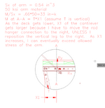
The profile of the calculation remains the same, what varies is T, the angle of T and X1 as shown below. T is generally well over a 1,000 lbs. My current project is 2,000 lbs. I don't see any product notes addressing this or showing a maximum cantilever. You can see in the original picture, I could slide the horizontal arm farther to the left until it touches the web of the girder, that makes X1 much longer. The concrete girders with wide and thin upper flanges are another issue. The arm is almost always below the flange. The reason for the post, I am not sure if I am worrying about something that is a non-issue with everyone else. Also, where someone connects the diagonal to the horizontal relative to the wheel load from the screed changes the loading to the vertical. One of my clients likes putting the joint under the screed wheel. That shoots all the force down the diagonal to the vertical.


1744210367656.png
 
On one hand, we treat C49s (and other overhang brackets) as a manufactured product -- we instruct our clients to follow the instructions and limitations of the manufacturer, and any nuances like this are between the contractor and manufacturer.

On the other hand, one of my projects just had a month delay because of one of these little "gotcha" moments. As bridge geometries change (and screed loads increase?), I'm not sure the manufacturers are keeping up documenting the limits required.

I presume you haven't had any help talking to Dayton?
 
I have not seen anything addressing this from any supplier. I cut the details I show here from a Dayton catalog, but there are other products with the same issue. The state wants stamped calcs on the overhang support "system". I have driven under other projects and have seen the horizontal arm touching webs but the vertical is still attached to the end of the arm. Some appear to be 9" to 10" at least from the vertical attachment to the hanger rod connection. Put just 1500 lbs at 10" and you get 15 in-kips. That gives 27 ksi in bending without adding the smaller gravity load from above. 33 ksi is probably the absolute max for an allowable. A combination of the distance from the hanger rod connection and the location of the diagonal-to-arm connection relative to the screed load has a noticeable effect on the stress.

Their usage charts are also an issue with me. While they show a 'depth" of the bracket, they do not detail the distance to the attachment of the arm. They generally show it at the end, but I see many that have been installed that do not have it at the end. Again, no notes that say do or don't.

As an example, Page 69 of my Dayton Bridge Manual shows 2 really bad Etch A Sketch looking drawings that show a dimension "A" in the area we are discussing. It looks like A is the distance from the End of the Arm and not from the Arm-to-Vertical joint. It shows it, refers to it but never quantifies it even though it states it does. Or, at least, I can' t find it.

I have inquired, but never got an answer. No being a "Customer" creates problems getting answers.
 
Dayton was very helpful and educated me on where Dimension A is at. It is specified at the "Bolt Holder" cut sheet. But it can be as high as 22" per the cut sheet. That is a long cantilever if you have a larger tension load coming up the vertical piece and attaching to the arm.
 

Part and Inventory Search

Sponsor