Continue to Site

Eng-Tips is the largest engineering community on the Internet

Intelligent Work Forums for Engineering Professionals

  • Congratulations cowski on being selected by the Eng-Tips community for having the most helpful posts in the forums last week. Way to Go!

Buckling of column in SAP2000 3

Status
Not open for further replies.

dccd

Civil/Environmental
Feb 19, 2021
150
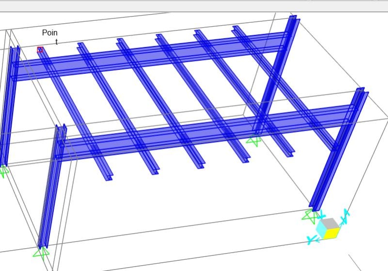
Hi , all. This is a steel frame made up of I-beam on top and I-beam column.

The I-beam on top is connected thru moment connection to the I-beam column below to restrain the major axis bending.

I understand that in major axis bedning of column (x axis)
frame_3_yngpbh.jpg
, it's pinned (bottom) , fixed (top) connection, so that k factor for buckling = 0.7 .

However, for minor axis bending ( y axis) , it's pinned free. In free condition, the frame shall be unstable, right ? But it seems that the SAP2000 still somehow detect it as pinned-pinned condition.

I have checked the buckling capacity of column, it's rather similar to the results that the SAP2000 gave. What's wrong with the model, can anyone help ?
 
Replies continue below

Recommended for you

I have checked the buckling capacity of column in the weak axis when Lcr = 1.0L , it's rather similar to the results that the SAP2000 gave. It's clearly show that SAP2000 detect it as pinned -pinned conidition. ...What's wrong with the model, can anyone help ?
 
dccd said:
I understand that in major axis bedning of column (x axis), it's pinned (bottom) , fixed (top) connection, so that k factor for buckling = 0.7 .

I feel that K > 2.0 given that the column appears to be a sway column with its bottom pinned and its top partially fixed.

dccd said:
However, for minor axis bending ( y axis) , it's pinned free. In free condition, the frame shall be unstable, right ? But it seems that the SAP2000 still somehow detect it as pinned-pinned condition.

I suspect that your joist members are acting somewhat like a moment frame beam with respect to weak axis column behavior. The response chain would be something like this:

1) When the tops of the columns try to rotate weak axis, they engage and rotate the wide flange girders in torsion.

2) When the wide flange girders try to twist, they engage and flex the attached joist members in strong axis bending.

You could adjust the model to behave as you'd like by releasing the torsional restraint at the ends of the girders. But, then, the model should be unstable as you said and you'd have to add some other kind of lateral restraint to make a go of it.
 
Do you mean the secondary member along the x axis act as restraint for the column in the minor axis bending ?

The seocndary member doesnt connect directly to the top of column, that's weird. How can the secondaty member act as minor axis bending moment restraint for the column ?

How to modify the model so that it will become more realisitic ???Since for the minor axis bending of column, it's clealy unstable because of the piined free condition, (no restraint against minor axis bedning on top of column)
 
By the way, if for major axis bending column is in pinned partially pinned condtion, the k shall be = 0.85, am i right ? The max k is only 2.0 ( free, cantilever condition)
 

Look to your picture carefully ... the major axis is X axis for the columns on the left and Y axis for the right columns..Regarding the joists; I suspect that the joists rigid connected to I beams..
 
Even if the joist (secondary beam) rigidly connected to the primary beam, will it have effect on the column ? The joist isn't directly connceted to the column. Will the joist act as restraint to minor axis buckling of column ?
 

The answer is yes... the torsional resistance of primary beams will provide some limited necessary restraint...But how the rigid connection will be provided and detailed is another issue..
Another question, is it reasonable to assume and model that rigid connection ?..


Do you mean the primary beam provide the bending moment restraint of the minor axis bending of the column ? There's only rigid moment connection between the beam and the column (in major axis of column) ...Will this affect the minor axis restraint ? Will the program detect the primary beam as minor axis restraint for column buckling ??


Or do you mean the secondary beam provide the bending moment restraint of the minor axis bending of the column ?

 
dccd said:
Do you mean the secondary member along the x axis act as restraint for the column in the minor axis bending ?

Yes, and I believe that HTRUKAK is saying more or less the same thing.

dccd said:
How can the secondary member act as minor axis bending moment restraint for the column ?

Like this if the torsion connection between the girders and columns is modelled as rigid.

KootK said:
The response chain would be something like this:

1) When the tops of the columns try to rotate weak axis, they engage and rotate the wide flange girders in torsion.

2) When the wide flange girders try to twist, they engage and flex the attached joist members in strong axis bending.

dccd said:
How to modify the model so that it will become more realisitic ???

Like this, if my assumption about the girder torsion connection is correct.

KootK said:
You could adjust the model to behave as you'd like by releasing the torsional restraint at the ends of the girders. But, then, the model should be unstable as you said and you'd have to add some other kind of lateral restraint to make a go of it.

dccd said:
By the way, if for major axis bending column is in pinned partially pinned condition, the k shall be = 0.85, am i right ? The max k is only 2.0 ( free, cantilever condition)

I don't believe that you are right if this is a sway frame, as your model suggests. For a sway frame with a pinned base and a partially fixed top: [2.0 > K >= Infinity].

I'd recommend supplying us with some more information:

1) Is your frame intended to be a sway frame in the X direction?

2) Is your frame intended to be a sway frame in the Y direction?

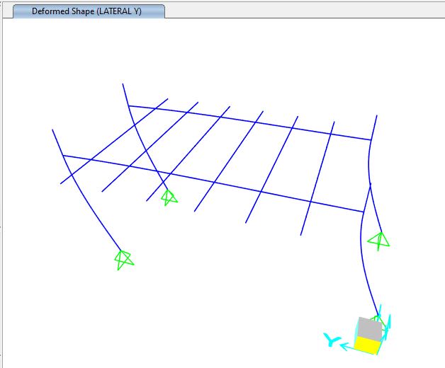
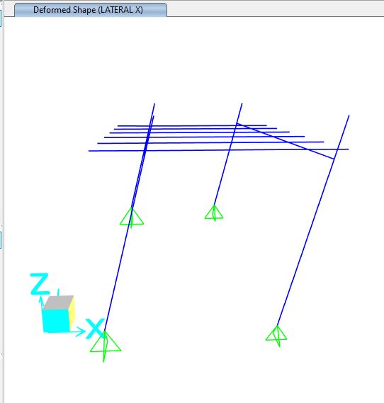
3) Can you post the deflected shape of your frame acting under an X direction load?

4) Can you post the deflected shape of your frame acting under a Y direction load?

5) Can you upload your SAP model so that we can review it it?
 
Do you mean that for when the column buckle in minor axis direction , the wide flange of primary beam is enagaged, so, somehow the buckling is prevented by the torsion resistance of the flange of the primary beam ?

However, in reality, is it reasonable to assume the wide flange of primary beam to act as restraint for minor axis buckling of column ??


As for the deflection shape of the column under the applied lateral load in x and y direction, please refer to teh attachment posted.

LATERAL_X_zq2vqp.jpg
 
The frame is intended to sway in x direction, for y -direction, they are rigidly connected.
 
You've said twice that you expect the structure to be unstable. What are you trying to achieve by modelling it? It seems as though half the story is missing.
 
Ya, I expect the model to be unstable . However, the model seems to be stable in the analysis software. I am confused now .
 
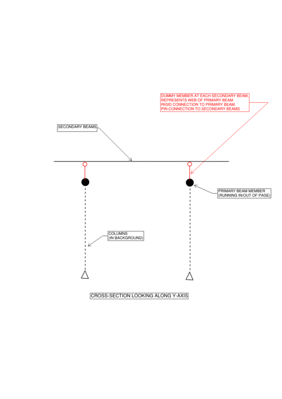
As per the comments above, you need to put more pin joints into the model to make it act the way you're thinking about it. Something like the picture below. You could also use master-slave node connections. You can't just put a pin in the secondary beams because they need to be continuous over the primary beams so the cantilever outstands remain stable.

Also, when a structure is a sway frame, the *minimum* value of K is 1.0. The maximum can be more than 2.0 as KootK said. 2.0 is just the largest number usually given in tables of idealised situations. The 2.0 case is for pin base with *ideal* rigid moment restraint at the top, but with the top free to sway. A real connection can't achieve perfect rigidity so K>2.0 in real structures.

UnstableFrame_lh25sz.gif
 
@steveh49 , I have tried to model a dummy member connecting the primary beam and the secondary beam to avoid the column detect the secondary beam as restraint of minor axis buckling of column ....

However, it seems the program still doesnt shows the real life situtaion, ( No member to restraint minor axis buckling of column, the column should fail in minor axis buckling , (due to pinned -cantilever condition in minor axis of column) .....
 
 https://files.engineering.com/getfile.aspx?folder=25ad72a8-9a75-418c-884c-77af6492eb44&file=0221_frame.$2k
I don't use SAP so can't look at your model. It should be unstable if you've put those pinned dummy members in so the analysis should fail before even getting to the code check. Some programs will stabilise an unstable structure by applying some arbitrary restraint. I don't know whether SAP follows this unsavoury practice though. Check the analysis log for any warnings or comments about stability.
 
Surprisingly, no warning message popped out. Whole structure is stable, that's weird.
 
Status
Not open for further replies.

Part and Inventory Search

Sponsor