Hi all--
I was wondering why the top and bottom flange width and thickness vary for built-up shapes. I have my own reasoning which is that moments vary along the length of the girder since it is a continuous structure. Also, if the bottom flange is thicker at one location and the section modulus is more for Sx- versus Sx+ then which section modulus would you use to calculate the bending stress of the girder at the maximum moment location. Or would I use the formula Mc/I instead and choose the larger c (at the thicker flange) since I stays the same.
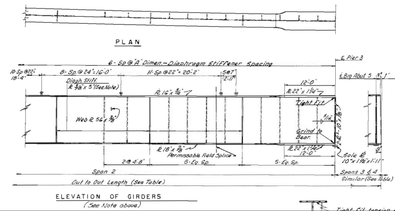
I have also attached a screenshot of the girder I am talking about. The girder in question has a much thicker flange at pier 3 which is because the negative moment at the pier is much higher than the positive moment at other locations. Any other thoughts or comments on why beam flange width and thickness vary along the length of the girder?
Thank you!
I was wondering why the top and bottom flange width and thickness vary for built-up shapes. I have my own reasoning which is that moments vary along the length of the girder since it is a continuous structure. Also, if the bottom flange is thicker at one location and the section modulus is more for Sx- versus Sx+ then which section modulus would you use to calculate the bending stress of the girder at the maximum moment location. Or would I use the formula Mc/I instead and choose the larger c (at the thicker flange) since I stays the same.
I have also attached a screenshot of the girder I am talking about. The girder in question has a much thicker flange at pier 3 which is because the negative moment at the pier is much higher than the positive moment at other locations. Any other thoughts or comments on why beam flange width and thickness vary along the length of the girder?
Thank you!