BCoop
Mechanical
- Jan 2, 2009
- 2
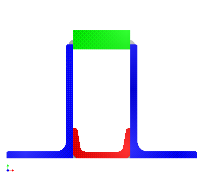
I'm replacing a load bearing wall in my house with a built up steel beam. Due to several issues (aesthetics, ease of installation, elimination of wood shrinkage. etc.), I've resorted to designing a built-up steel section. The beam is constructed of two L6 x 3.5 x 3/8 with a C3 x 6 and a 3 x 1 bar as shown below.

I've considered all loads acting on the beam and have calculated shear and bending moment diagrams. The built up section has Ix = 75.8in^4 and a "web" area of 4.5in^2. The max normal stress is 15ksi and the max shear is 8250lbs. Max deflection is l/445. The beam is supported from below by a masonry wall on one end and a 3.5" dia structural steel tube column on the other. Both the wall and the column only support the angles and impart no load on the channel. There is also no load sitting on the 1 x 3 bar - 2x8 floor joists rest on the legs of the angle and are braced to prevent twisting.
My question regards how to design the welds holding the beam together. I have calculated the principal normal stress in the upper weld at the point of maximum shear as if I were determining stress in a W section's web where it intersects with the flange, but I don't feel like what I've done takes into account the size of the weld - it assumes shear is uniformly distributed in the web.
With full length fillet welds I've calculated 1.97ksi normal stress which seems to indicate I can call out a 2-6 stitch weld instead without any concern, but I just want to make sure I'm doing things right before I submit my plans to the county for approval.
I know I could(should?) consult with a licensed structural engineer, but with the exception of the weld spec I don't feel like I'm in over my head.
Thanks for any help.
