Eng-Tips is the largest engineering community on the Internet

Intelligent Work Forums for Engineering Professionals

  • Congratulations waross on being selected by the Tek-Tips community for having the most helpful posts in the forums last week. Way to Go!

Bulkhead in flood zone V

Status
Not open for further replies.

Prestressed Guy

Structural
May 11, 2007
390
0
0
US
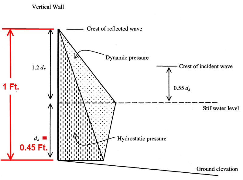
I am working on a very small bulkhead and the AHJ is requiring that it be designed for Flood Zone V. The wall is a freestanding log bulkhead with a 1' exposed height and is 50' shoreward of the high tide line so it almost never gets any water on it. The only time that the water gets there is at extreme tides combined with wind waves. The property owner says that has happened only once in the last 20 years. the main function of this wall is to provide a demarcation between the beach sand/native vegetation and his lawn.

How do you calculate the load on the wall in these conditions? All of the calculations in ASCE-7 section 5.4 deal with ds with is the local still water depth and they do not seem to apply to a wall that is normally high and dry.
 
Replies continue below

Recommended for you

That is the section I have been looking for but have been unable to figure a way to calculate ds (local still water depth). Equation 5.4-3 sets ds = 0.65(BFE-G) but I cannot find where to get BFE or G. The property owner has a survey but it is a plan survey and does not provide any elevation info.
 
I received word from the AHJ that the BFE for this site is +13' which puts it about10' above the top of my little wall. am I correct in assuming that I truncate the load diagram at the top of the wall and use that for the pressure on the wall? This is based on the potential for tsunami at this beach. Of course if that ever happens the structure behind the wall will be toast but as least the wall will be ok.[noevil]
 
you will have 10 feet of water on both sides of the wall. net lateral force will be zero. pressure will be equal to 10 feet of water (about 4.3 psi). you will have a much worse lateral loading prior to the big wave. as the water level rises you will have wave runup and breaking waves hitting the wall.
 
Haydenwse - IMHO, it is time to take a semi-graphical look at this problem. ASCE 7-10 appears to assume that the still water depth (d[sub]s[/sub]) plus the height of the reflected wave (1.2 d[sub]s[/sub]) is always less than the height of the wall. That is not true for this problem.

The wall is 1 foot high, with backfill.

From the diagram below, the worst case breaking wave loading will occur when d[sub]s[/sub] is 0.45 feet above the base of the wall. If d[sub]s[/sub] is higher, the waves just wash over the top without exerting any force on the wall. If d[sub]s[/sub] is lower, the crest of the reflected wave does not reach the top of the wall.

ASCE_7-10_-_Wave_Pressure_lifgrc.png


Using C[sub]p[/sub] = 1.6 (Risk Category I), Unit Weight of Sea Water = 64 pcf, and solving the equations (5.4-5) and (5.4-6), I get:

P[sub]max[/sub] = 81 lb / ft[sup]2[/sup]

F[sub]t[/sub] = 54 lb / ft

[idea]
[r2d2]
 
note that it may be prudent to assume some scour at the base of the wall. that may be a more likely failure mode and it will reduce the stability against wave action. also, you might assume some uplift if the soil is saturated
 
I would like to make sure I understand the application of equation 5.4-5 and 5.4-6. It appears that both are describing the same force. Pmax sets the max point of the pressure and Ft is the resultant of that pressure diagram. It seems to me that Pmax is just given to show how Ft was derived and that the pressure and force are not additive.

If this is correct than you just need to apply the 54 plf load at the Stillwater height.

If they are additive than the wall would be designed for 2*54 plf
 
 http://files.engineering.com/getfile.aspx?folder=2d998883-6fd8-4681-8fae-49ac32029bf0&file=load_on_wall.png
Haydenwse - Figure 5.4-1 is a simplification of a breaking wave, but a pretty good one. The two equations give accurate results based on the assumptions.

P[sub]max[/sub] (lb/ft[sup]2[/sup]) and F[sub]t[/sub] (lb/ft) both have to be considered individually to design the wall. This 1 foot high wall could be somewhat confusing since it is so short; not much pressure or force.

It may help to consider at more typical height wall, say 6 feet. Then, d[sub]s[/sub] = 2.73 feet. From this I get:
P[sub]max[/sub] = 490 lb/ft[sup]2[/sup]
F[sub]t[/sub] = 1984 lb/ft

With these numbers, it may be clearer that designing a wall for a pressure of 490 lb/ft[sup]2[/sup] is different than designing a 6' high wall for a total force of 1984 lb/ft. The wall has to meet both of these criteria.

[idea]
[r2d2]
 
Status
Not open for further replies.
Back
Top