Eng-Tips is the largest engineering community on the Internet

Intelligent Work Forums for Engineering Professionals

Bulkhead-Longeron Connections? 2

Status
Not open for further replies.

VN1981

Aerospace
Sep 29, 2015
186
0
0
IN
I am kinda starting this question very vaguely. Let's say that I am curious to learn ways of connecting between longerons & bulkheads in the fuselage. The aircraft is an UAV and I have drawn not an exact but typical representation of current connection setup.

01a_nxrshl.png


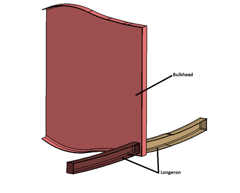
What I have omitted from the above image is the skin (which sits below the bulkhead & the longerons) & also other longerons and the bulkhead is not “complete” as well. The current connection involves bolting the 2 longerons & the web of the bulkhead together.

02_ytri9p.png


03a_ecttuh.png


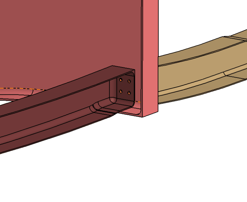
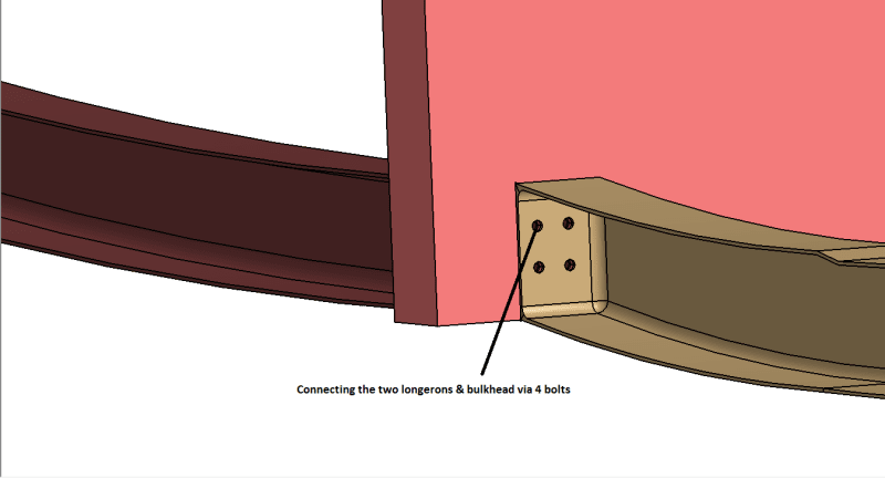
I am not familiar a whole lot on the load path in the fuselage, but my current understanding is that longerons carry axial & bending moment i.e. they act as a beam with supports at the bulkhead and the loads (at least bending ones) are dumped in to the bulkhead. If my understanding is correct, with that in mind, I think the 4 bolts are capable of providing the load path to transfer moments & shear in to the bulkhead while the axial load path is maintained from one longeron to another via bolts (?)

Also, are there any other type of connections which would work if my understanding is correct? For example, could any sort of clips be used? I guess, what I am asking is that what are the typical types of bulkhead-longeron connections used in non-commercial aircraft?

Thanks...
 
Replies continue below

Recommended for you

It is not uncommon for the bulkhead to have a cut out and the Longerons to be continuous with clips attaching the bulkhead to the longeron.

B.E.

You are judged not by what you know, but by what you can do.
 
The longitudinal joint as shown appears flexible and weak. If you HAVE to break a longeron the joint should be made with extruded cleats (or maybe C-fittings) joined longitudinally by bolts. A normal longeron is continuous through a simple bulkhead and joined to it by shear cleats with at least three fasteners per cleat. This is also true for normal fuselage frames.
 
That joint is terrible. Not going to sugar-coat it. Thank you for taking the time to show us what you mean, though.

If you were to purchase a book called "Practical Stress Analysis" by Flabel you would be treated to hundreds of illustrations of structural connections that work, accompanied by explanations of how they work.

No one believes the theory except the one who developed it. Everyone believes the experiment except the one who ran it.
STF
 
Sparweb,
I did not design that joint. Let me just say that joint shown is existing and I am trying to learn the pro & cons of the same and in the process, try to learn on how to design better ones. I do have Flabel book with me...gotta go through it again.

RPStress, as I mentioned, the aircraft is an UAV and not a commercial one.

Anyways, looking at this F-16 cutaway diagram (link below...image too big to post inline), can anyone let me know how are the longerons connected to bulkhead? I can't make out if the longerons are passing through the bulkheads via cutouts in the bulkhead web, especially in the region just fore of Engine.

 
Most General Dynamics designs would have continuous longerons with cutouts in the BH to allow them to pass through. This is based on fairly recent designs I've seen from GD, and their design handbook from the 70s.
 
my 2c ...

whilst not a great joint, I don't know I'd call it "terrible".

what loads are going through the longeron ? what loads in the bulkhead ?

Can the longeron function as simply supported at this location ? (and so this joint is shear effective only)
If you do need bending continuity, then adding a tension clip (bathtub fitting) on the inner cap would improve things.

Is the bulkhead accurately shown ? what, no sitffeners ?? no lightening holes ?? (if so, then that i'd call "terrible".)


another day in paradise, or is paradise one day closer ?
 
RB,
If the bolts are of Tension head type, then joint should be capable of transferring tension as well as shear loads?
Yeah, I agree with you on adding tension clip. Also the bulkhead is not accurately shown. There are stiffeners although no lightening holes at this stage of design!
 
all bolts have some tension capability. I'm assuming Hi-Lites, for good hole fill and better shear. But I think we're all looking at the impact of local bending on the very simple bulkhead and going "ooohh?" But we don't know the magnitude of the loads nor the sign, nor the design decisions that drove the design down this road.

A mouse hole in the bulkhead and shear clip to the longeron would be better design for the longeron, and better for the bulkhead too.

another day in paradise, or is paradise one day closer ?
 
Here is the Frame-corner/longeron intersection design that I am familiar with...

[URL unfurl="true"]https://res.cloudinary.com/engineering-com/image/upload/v1535132919/tips/Frame-Longeron_Corner_Design_fk1cud.pdf[/url]

Regards, Wil Taylor

o Trust - But Verify!
o We believe to be true what we prefer to be true. [Unknown]
o For those who believe, no proof is required; for those who cannot believe, no proof is possible. [variation,Stuart Chase]
o Unfortunately, in science what You 'believe' is irrelevant. ["Orion", Homebuiltairplanes.com forum]
 
Cannot seem to avoid adding my comments to this issue ..
Design is a nice initial objective for the 'office boys' - but my perspective always involves the repair 'addendum' - something that is rarely considered these days .. In today's 'my problem ends when the aircraft leaves the shop' world; has anyone considered the in-service replacement of the bulkhead? The design initially provided would be a failure - requiring significant disassembly & Mr. Taylor's design would be acceptable .. Should the aircraft be damaged; has any consideration been given to repair or replacement.

I am still in awe at how little communication there was between the designers & the in-service engineers. For example an early series had a crack at a floor / formed-frame intersection. They redesigned the structure with machined frames but managed to incorporate the same crack in their latest design. No one seemed to have the time (or concern) to review some history of the area ... and /or in their minds .. "not my problem"
 
Edmeister...

I get where You are coming from... the lessons learned from best practices and experiences don't ever seem to be re-incorporated into the current design... and when failure occurs, then repair becomes difficult to impossible... resulting in need to repair/replace structure that is embedded so deeply as to require heroic efforts to repair/remove-replace [RRR]. The situation is bad [but usually getting somewhat better] for aircraft still in production... but getting a LOT-worse for aircraft out-of production and getting older-by-the-day.

I've worked on antique [out-of-production] military aircraft my entire career. We have relatively few fatigue issues that aren't directly related to the ancient materials incorporated into the original designs, IE: thick structural parts MF 2024-T3 [-T4], 7075-T6, 7079-T6, 7178-T6, 4340-air melt steel, magnesium sheet/wrought/cast parts, etc... with old generation manufacturing practices and protective coatings. Yeah... there are poor design details that contribute to early fatigue-crack initiation... but 'bad actor materials' prevail... poor KIc, relatively rapid crack-growth [low toughness], poor/low stress corrosion cracking [SCC] threshold, and poor exfoliation corrosion [EXCO] resistance... and generally no improvements from shot-peening or mechanical improvements to the surfaces. And guess what... each area of the structure is built around a core structure element that is deterioration prone... and requires heroic efforts to RRR.

In our case we liaison/service engineers are stuck with what we have... even incorporating new materials on the old structure is a great idea**, until You remember that the old remaining structure trumps the new. In our case we don't dare install conventional interference fit solid shank fasteners... only net-fit ['transition fit' in some vocabularies].

*** In many cases older alloys or forms [die forgings, extruded-profiles, castings, etc] in the original alloys simply can't be procured anymore.

NOTE. The following aircraft I'm aware of experienced catastrophic failures due to materials issues and were/have-been mostly/completely retired from USAF/USN service due these 'bad actor' materials [aggravated by associated poor design details and how fractures initiate and grow in these materials]...

A-6, A-7, B-47, early model B-52s, F-4, F-5, early model F-16s, C-5A, early model C-130s, C-141s, etc... Horror stories mostly.

Aircraft still in-use with significant parts/materials/structures upgrades to be 'safe' are T-38, CKC-135Rs, B-52Hs, early model F-15s etc.

More later... if interested... duty calls.


Regards, Wil Taylor

o Trust - But Verify!
o We believe to be true what we prefer to be true. [Unknown]
o For those who believe, no proof is required; for those who cannot believe, no proof is possible. [variation,Stuart Chase]
o Unfortunately, in science what You 'believe' is irrelevant. ["Orion", Homebuiltairplanes.com forum]
 
OH... YEAH... and the F-111... loaded down with 7178-T6 and 7079-T6 and D6AC VHS Steel primary structural members.

NOTE. The acft I work on still has 7178-T6 extruded and sheet/plate structure. All 7079-T6 DF parts have pretty much been replaced. We treat 7178-T6 very carefully and don't hesitate to replace it... with parts MF 7050-T7451, 7150-T7751, 7055-T77511, 7136-T76511, etc... for anything more than very small/repairable defects... since onset of minor/early defects predicts the avalanche to follow.

What is really awkward is that 7178 and 7079 alloys did evolve SCC/EXCO resistant tempers... still with really poor fracture toughness and crack-growth... but the process had to be accomplished in-line-with SHT/quench/aging-bake... unlike 7075-T6 being HT from -T6xxx to -T73, -T76... which generally can be done with an added 'over-aging-bake cycle'. NO WAY to take in-service parts and just 'over-age-bake' to T7xxx. DANG.


Regards, Wil Taylor

o Trust - But Verify!
o We believe to be true what we prefer to be true. [Unknown]
o For those who believe, no proof is required; for those who cannot believe, no proof is possible. [variation,Stuart Chase]
o Unfortunately, in science what You 'believe' is irrelevant. ["Orion", Homebuiltairplanes.com forum]
 
Hopefully i am not leading off topic ..
My greatest peeve is a recent regional jet where the 1-peice radar bulkhead and fwd pressure bulkhead are located inside the fwd sloped nose cone of the aircraft. Given the convex nosecone shape & sloped bulkhead flanges to accommodate .. there is no possibility of replacing either item without peeling back several feet of side fuselage panel & somehow enlarging the opening for the correct diameter for bulkhead insertion. These items are both 1-peice machined, limiting any type of repair ... and what is most hilarious, is that the radar bulkhead has huge openings for weight saving. I can visualize the goose (bird) crashing through the radome, managing to line up with one of these radar bulkhead openings and ricocheting off the fwd bulkhead (only 8" away). And when this happens .. no less than 6 months of RRR! (as Mr Taylor refers to it) .. Should they have designed the bulkheads as an assembly of smaller parts / individual parts would have been much easier to RRR. ... or per my previous post .. had any of these engineers reviewed past experiences with bird impact; they could have anticipated the result - and selected a more feasible assy for field repair...
 
edmeister... hope this makes sense...

Bird-strike threats are relative to mission, flight envelope, flight level, true speed, terrain/environment, etc.

IF there is a high incident-probability of bird-strike... or a high probability of substantial damage from a bird-strikes, then the RADOME and its attachments are Your first line of defense for preserving the integrity of the pressure bulkhead.

NOTE. In this case the radome and radar antenna/base are sacrificial.

NOTE.
The radome should adequate strength to survive the expected impact without shattering or experiencing straight-line bird penetration thru to the bulkhead. Regardless, the radome attaching structure [frame edge] should either be: (a) 'easily repaired'; or have replaceable elements intended for absorbing damage just short of affecting the primary structure; or (c) be made bird-strike damage resistant by added structural shielding/armor.

Regards, Wil Taylor

o Trust - But Verify!
o We believe to be true what we prefer to be true. [Unknown]
o For those who believe, no proof is required; for those who cannot believe, no proof is possible. [variation,Stuart Chase]
o Unfortunately, in science what You 'believe' is irrelevant. ["Orion", Homebuiltairplanes.com forum]
 
noted, but "should" ! much as Ed said, "could".

Maybe Ed's design was carefully considered and the cost of repairing a few airplanes was considered worth the savings.
And, yes, I'm having tea with the Queen (as in Lewis Carroll) this afternoon !?

another day in paradise, or is paradise one day closer ?
 
Ed, instead of trying to replace a one-piece bulkhead with another, and doing (as you say) lord knows what sort of damage to the skin panels, you could design a multi piece bulkhead.

and if you've had a bird strike, what damage to the surrounding panels ? maybe replace everything, maybe to a couple frames aft ??

another day in paradise, or is paradise one day closer ?
 
rb1957 ..
Skin panels are usually large skin panels .. replace / splice / or scab as required is usually done. But the bulkheads are another story. The impact usually buckles or distorts the shape - thus replacement of bulkhead easier than machining custom widgets to fill-in the damage cutout - & thus we have the problem! The 'UN-pressurized' radar bulkhead is obviously easier then the fwd bulkhead to repair. Fairly easy to get most repairs approved. But the fwd Bulkhead due to damage tolerance considerations will only allow the 'pettiest' of repairs. The OEM just shrugs & and determines "replace'. Also note we have avionics, instrument panel, & nightmare galore one the aft side of the fwd bulkhead. The old days where bulkheads used to be made from multi-part assemblies were the best solution. Today, 1-piece machined 'ingots' of aluminum may be initially cheap to mfr & install .. but quickly get expensive to repair.
bulkhead_hoiw03.png

Also .. if a crack shows up in a multi-piece assy, repair usually consists of replacing the crack component. Today, when a machined bulkhead gets a crack, get out the CNC (to fab custom repair widgets) & hope there are nearby areas / spaces / landings where fasteners can be installed & access is available (see above about nightmare galore). !
Attached pix is a simple repair to a machined radar bulkhead. Lots of room & space to work with. Option to replace bulkhead also considered. An early version of same bulkhead 'multi-part assy' would just have required the replacement of a few parts. What an extra chore !
 
Hmmm... Doesn't look like most pressure bulkheads I'm familiar with.

SWAG...

I will bet You that if fatigue cracking is really an on-going problem with these airframes, after X-hours, then it was probably validated/discovered during the fatigue testing... IF an honest pressure/flight-fatigue test was actually accomplished... and was [probably] evident in the fatigue test report. The engineering judgement call at that time was [probably] 'to repair using conventional means/methods'. NOTE. IF the radar antenna system and its attachments were not applied to the web at time of fatigue testing... including any vibration modes... then it was an 'unfair test'.

WHY do I say this? Awhile back... as I recall...

One of our 'high time jets' developed fatigue cracking damage on a fuselage pressure web that blew-out suddenly and caused a serious IFE with major fuel loss [in-flight-fire potential]. Problem-was that when the blow-out occurred, the unpressurized bay AFT of the web was suddenly pressurized... and contained a full fuel bladder cell. The cell was squeezed by the sudden pressurization and was cut/torn-open by the sheet metal rupture ['sharp-edge flap of sheet-metal'] which rapidly flooded the cavity and back-flowed fuel into the 'now unpressurized avionics bay'... which then took a while to drain overboard. Thank God for JP-8!

The mishap was scary and the repair was not 'a-piece-of-cake'.

For giggles, I dug thru a bunch of old/dusty fatigue test documents on the fuselage. Funny thing... there was a fatigue-test failure on exactly the same pressure web-area within ~a-very-few-test hours of the actual in-flight failure. Since it was a sheet metal web, and the damage was not catastrophic it was judged/considered 'at that time' to have an acceptably low structural risk... and was 'easily detected and repairable'.

Needless to say, this web became the focus of a mandatory structural inspection and subsequent mod-repair before X flying hours. Also one of the fatigue guys went thru the old report(s) looking for any similar 'findings' on sheet-metal elements not otherwise well understood/analyzed by DADTA.


Regards, Wil Taylor

o Trust - But Verify!
o We believe to be true what we prefer to be true. [Unknown]
o For those who believe, no proof is required; for those who cannot believe, no proof is possible. [variation,Stuart Chase]
o Unfortunately, in science what You 'believe' is irrelevant. ["Orion", Homebuiltairplanes.com forum]
 
yes, the interactions between structures and systems can easily be missed.

my 2c ... the impact of radar vibration on the bulkhead should, sorry "should", be small enough to neglect compared with pressurisation loads. I don't think I've ever seen a fuselage fatigue test include the weather radar, operating and loaded by inertial loads. I'd've thought that if the attachment was flexible enough to cause a structural problem, then it should also show up in the system.

another day in paradise, or is paradise one day closer ?
 
Status
Not open for further replies.
Back
Top