Eng-Tips is the largest engineering community on the Internet

Intelligent Work Forums for Engineering Professionals

Bye-pass rotameter installation 4

Status
Not open for further replies.

Asisraja D

Mechanical
Jan 3, 2024
138
0
0
IN
Hello professionals
This forum has helped me a lot and again i thank you all for helping me in this.
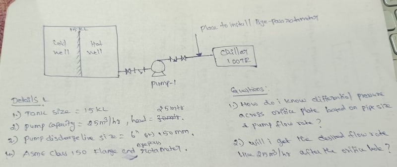
we have planned to install a bye-pass rotameter in our chiller piping (Hot well to chiller).
The problem arises when we talk to vendor about bye-pass rotameter he introduced us about Differential pressure across the orifice plate.
As he told us there is no possibility of direct fitting of flange type bye-pass rotameter in our system because in vendor's catalogue for 6" pipes the minimum flow should be 136 m3/hr then only we can get 50 inches of water column as differential pressure across the orifice plate. i am totally new to this installation technique and currently we have no options to change the pump capacity. we have pump capacity of 25 m3/hr and 25 meter of head. i have given the vendor's data and our piping data in the attached file. i have some doubts on this and i will ask them below:

1)if the pressure drop across the orifice increases does it affect the desired pump flow rate ?
2)if differential pressure is based on orifice plate diameter then how can i decide the orifice plate diameter ?
3)is there any alternative way to reach that differential pressure as per vendor's catalogue in our 6" piping line ?

i know your time is priceless and i am sorry if i made any mistake in this concept, please help me when you are free to read this.

Thank you all.

 
 https://files.engineering.com/getfile.aspx?folder=2c410e0c-5b73-4204-b500-7ca03d2ee7a4&file=piping_dwg.jpeg
Replies continue below

Recommended for you

1.) Increasing pressure drop increaqses the flow through the orifice.
2.) You must know any 2 of the 3 principal variables,

1) Orifice diameter,
(The internal pipe diameter orifice is fitted to should be approximately the Orifice_diameter /0.65)

2) Pressure Drop across the Orifice (Note that 1 inch of water is a pressure of (62.4/1728) psi or about 0.0361 psi, or 1 inch of water = 0.248843 kPa)

3) Flow Rate.

And density and viscosity of the liquid properties

Then you can try this calculator.


If you do not have pressure, (25m is about 2.5 Bar, a lot more than enough) you must
1) lower the orifice deeper under the liquids free surface, or
2) Increase the height of the liquids surface above the orifice, or
3) Provide a pump to increase pressure.


--Einstein gave the same test to students every year. When asked why he would do something like that, "Because the answers had changed."
 
While your beta ratio is within acceptable range, making it higher will increase your metering accuracy and reduce the 50 inch pressure drop. This link suggest beta = 0.6

Can you post a sketch of your piping showing pressures and where you will put this orifice meter. Note that you should have a straight length of pipe > 10 diameters before and another length of at least 5 diameters after your orifice meter. Those should be as long as possible.

--Einstein gave the same test to students every year. When asked why he would do something like that, "Because the answers had changed."
 
It is not clear what you mean. It appears you are referring to the orifice plate as the bypass rotometer and visa versa as if it is the same device. If this is the case then the vendor data shows for a 6" rotometer the minimum flow for 6" size is 136 m3/hr. A flow of 25 m3/hr in a 6" pipe is super low flow/low velocity. There is something wrong with your line size or you the flow is a lot greater than 25 m3/hr.

Anyway to size the rotameter you have to go by the vendor tables which indicates that a 2" or 2 1/2" rotometer is the correct size for the 25 m3/hr flow. For a 2" the pressure drop is about 175 inches water gage or 4.4 meters head loss. This is additional head loss to your system with the rotometer installed. This additional head loss plus the head loss in the piping at 25 m3/hr cannot be greater than the 25 meters of available head from the pump or the flowrate will be reduced below 25 m3/hr.
 
hi,
A sketch please!
Do you know what a by-pass is?
A calculator is a tool, if you don't understand what it is doing, you are in trouble!
Pierre
 
This was attached to the first post. I just saw it today.
piping_dwg_bygshr.jpg


--Einstein gave the same test to students every year. When asked why he would do something like that, "Because the answers had changed."
 
For this level of flow this type of meter is not good idea.

The meter works by diverting a small amount of flow upwards through the vertical tube, lifting a small tapered plug in a tapered tube with more flow equating to a higher position of the plug. The pressure differential to get this flow to flow is induced by the orifice plate.

It looks like vendors only work in certain maximum fixed differential pressures. Th smallest seems to be 50 inches water column which in a 6" pipe equals 136m3/hr.

So your 25 m3/hr would be right at the bottom of the range and hence its uncertainty would be quite large.

So you know the flow rate that the vendor uses - 136 m3/hr, you know the differential pressure they are generating at that flow (50 inches water column) so you can determine the orifice size the vendor uses. I can't see though why you are designing or calculating the orifice here - that's what the vendor does so that the flow indicated by the meter is correct. Put the wrong size orifice in and the meter won't read correctly. The vendors sell different graduated tubes depending on what option / max flow you have. So if you buy a package of orifice meter and rotameter with 50 inches wc and it's half way up, the flow will be ~67 m3/hr. Buy the 200" WC version and half way up would be ~ 135 m3/hr. The orifice and meter comes as a package.

So yes, this will decrease flow a little bit because you are introducing a pressure drop.
But this will be a lot less than 50 inches water column because you are flowing at only 20% of the max flow.

Hence why this is the wrong type of meter or you need to replace a section of your piping to 3" to get a meter which works better.

does that help?

Remember - More details = better answers
Also: If you get a response it's polite to respond to it.
 
1503-44 sir this is new piping system and I work in Greenfield projects so we still didn't include pressure gauges and electrical supply so I have show the position of orifice set up (flange tapping method) as you told this is little bit hard to provide 10 times of pipe dia as straight run excluding riser length before the orifice set up but it is overall 1.2 meter including discharge riser length. Is this enough to create pressure drop across the orifice set up?

pierreick sir I don't know how to provide sketch can u please check this image I attached here.
 
 https://files.engineering.com/getfile.aspx?folder=010bc997-9419-4931-8558-efafb96dca64&file=IMG_20240321_210835.jpg
the 10D thing is about uncertainty, but less than that won't make a massive impact.

The fact remains that your meter will be at a small section of the range. Far better to insert a section of 3" pipe, then you will get 10D in a shorter space than in your 6" pipe.

Remember - More details = better answers
Also: If you get a response it's polite to respond to it.
 
LittleInch
So yes, this will decrease flow a little bit because you are introducing a pressure drop
But this will be a lot less than 50 inches water column because you are flowing at only 20% of the max flow.
It helped a lot but I couldn't understand this ?

Am I getting only 20% (5 m3/hr) of flow from my maximum flow rate (25 m3/hr)?

I could not get this sir can you please explain me a little bit 🙏
 
LittleInch sir
Far better to insert a section of 3" pipe, then you will get 10D in a shorter space than in your 6" pipe.
We have already installed the 6" pipe towards the chiller circuit so it is bit hard to change the entire pipe size 😔.

This is happened because of one of our senior project managers told to install this method but he didn't tell us any exact location to fix the orifice set up.

 
Sorry. Poor wording.

What I meant was that at 25 m3/ hr, you will only be at approx 20% of the range of the flowmeter, which goes from 0 to 136m3/ hr.

Anyway in your OP I believe the vendor is incorrect. It is not the "minimum flow" which is 136m3/ hr, it's the MAX flow or range of the meter. But can you attach the whole of the catalogue, not just one little bit.

Remember - More details = better answers
Also: If you get a response it's polite to respond to it.
 
Hi,
As suggested above you should insert a smaller pipe to your system to cope with the flow meter size, if you confirm 25m3/h in a 6" pipe or consider changing the pipe size to match the flow meter dimension.
A better option could be to use a nonintrusive flow meter, let say Doppler effect technology.

Good luck
Pierre
 
Status
Not open for further replies.
Back
Top