Continue to Site

Eng-Tips is the largest engineering community on the Internet

Intelligent Work Forums for Engineering Professionals

  • Congratulations SSS148 on being selected by the Eng-Tips community for having the most helpful posts in the forums last week. Way to Go!

Calculate Duct Pressure From Inputs and Output

Status
Not open for further replies.

chris341

New member
Jun 22, 2023
4
This was originally posted at the engineering stack exchange.

I am currently modeling a high fidelity simulation of the Boeing 747-200 for a flight simulator, and I am now at the stage of programming what is essentially the HVAC system for the aircraft.

I will try to keep aviation jargon out of this unless it is necessary, for simplicity's sake.

Here is what I know about the system:

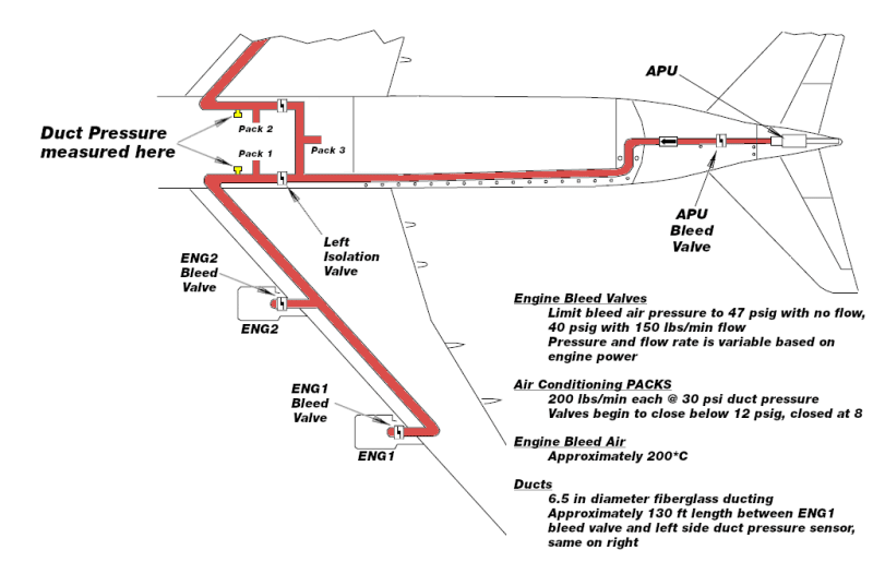
The aircraft has four engines, each of which can supply compressed air to the main air conditioning supply duct. The pressure (in PSI) of the air in the duct is directly output to a gauge on the flight engineer panel, and it is this gauge output that I am ultimately wanting to arrive at.

The compressed air from each engine is controlled via a regulator valve to a maximum of 47 psi with no flow, and 40 psi with 150 lbs/min flow (which seems to be the design maximum flow for each engine but I am not sure of this). With all four engines running, the theoretical supply is thus ~600 lbs/min.

There are 3 air conditioning units (PACKS in aviation terms) that are connected to this air conditioning supply duct, each can be turned off or on individually.

These air conditioning units are controlled semi-automatically, and require a minimum of 8 PSI in the duct to run (the poppet will force the valve to close if the duct pressure is less than 8 PSI). The valve also controls the mass flow rate into the air conditioning unit: according to my manuals, the AC Pack valve is fully open above 12 PSI until duct pressure exceeds ~30 PSI, and each pack attempts to regulate mass flow to approximately 200 lbs/min.

The ducting between the engines and the point at which the pressure is measured as well as where the AC packs are supplied is 6.5 inches in diameter and made of fiberglass. The air supplied by engines is routed through a pre-cooler in the engine itself that cools the air to approximately 175C, and this is approximately the temperature of the air at the point where pressure is being measured. The duct has a design leakage rate of about 300 SCFM at 45 PSI.

What I would like to calculate is the duct pressure, as it would be indicated on the flight engineer's gauge, based upon the inputs and outputs of the system. The gauge measures the pressure of the air just before entering the air conditioning manifold system (temperatures and pressures as mentioned above). What formula or set of formulas can I use to determine what the pressure in the duct is at any given moment based upon the input and the output of the system?

Thanks! Chris
 
Replies continue below

Recommended for you

Each component that you describe, and many more that you don't, has its own flow vs. pressure drop characteristic.

Some of the components that you describe, and others that you don't, actively control flow or pressure.

Gather all of the characteristics and solve simultaneously for the pressure that you are interested in.

Conceptually, described in three simple sentences. The implementation may be non-trivial.

An empirical approach would likely be simpler.

Somewhere in the combined archives of Boeing and the Pack manufacturer (Honeywell I think) will be development and qualification test records that probably have enough data to use as a starting point for an empirical solution.

Without a sponsor with some serious clout I doubt that you'll get access to those archives.

Does your product really need this level of detail, or do you just hope for it?
 
My product definitely does not require an extreme level a detail, but the more detailed/accurate I can get, the happier I personally am [smile]

An empirical approach is probably the simplest way, and indeed I am willing to accept a vastly simplified version of the system provided it can reasonably approximate the real one, or in other words, the pressure is never outside of what might potentially be expected at any given moment.

I had the idea today that rather than treating this duct like a duct, I could treat it like a pressure vessel, since pressure is what I am attempting to get a reading of. Could the following formula be used to describe the duct pressure with simple inputs and outputs?

P = (RT/V) x integral of sum of inputs and outputs over time
where
P = Pressure
R = Universal gas constant
T = Temperature of input air
V = Volume of the duct system
 
I don't think so. The ideal gas law doesn't have any terms that deal with flow induced friction losses, which likely dominate this system.

 
But you've just said that the input is between 47 and 40 psi into the units.

This pressure will be controlled probably by the bleed port off the engines as you describe. More flow it opens up a bit more, less flow is closes down.

Air bleeds are a major source on long distance aircraft of engine lower efficiency so they try to minimise the flow when they can (I think)

Sometimes on take off when they want full power you hear the a/c in the cabin reduce to virtually nothing and it all goes into the engine.

Draw out what you know of the system where the regulating is taking place and where the guages are. My guess is the flight engineer will only want to know there is air coming in at 40 psi.

Remember - More details = better answers
Also: If you get a response it's polite to respond to it.
 
Please tell me this is school homework and won't be used for an actual flying airplane with humans in it. Ideal gas law really has not much to do with this. Your system also doesn't use "ideal gas", it uses air. You'll need to use the properties of the actual fluid use (air, and probably air at lower density assuming the airplane flies way above seal level).

Look up how duct systems are designed and apply those principles to your system. There will be differences since it seems pressures are much higher, and velocities likely as well. I assume compression of the air will matter at those pressures (we neglect that in typical HVAC ducts since the pressures are very low, just a fraction of a psi). But ultimately you need to know the sizes, bends and internals of the hoses and all devices. There also will be control valves etc. adding pressure drop.
 
@MintJulep fair enough, that was not something I had considered but it does make sense. My research continues...

@LittleInch, yes this is very true, airflow from the engines does reduce efficiency because the compressor has to turn faster (and therefore use more fuel) to generate the same thrust as the engine would make without air bleeds active. I will try to come up with a diagram of the system that is based on what the maintenance manuals show me to better illustrate what I am after.

@HVAC-Novice, This is not 'school homework', but also neither is it serious by any means. It is a personal flight simulator project that I would like to seek the highest accuracy I can with as a single software developer.

I have tried researching in great detail how various duct systems work but obviously this field is very complex and I am by no means even educated on how such systems work. The idea to treat the duct as a pressure vessel was merely and idea, since I do not know exactly how these systems and interactions work empirically (i.e. in a way that can be mathematically simulated).

As stated before, my research continues. Thank you all for your responses, I do want to emphasize that I appreciate any and all assistance, especially as this is merely a personal project with no real world implications.

 
the bleeds take mass from the flow through the compressor stages, which then means the EGT at the 1st turbine stage increases which means they have to reduce the fuel flow to keep it inside limits which then reduces the N1.

The way they work is when at a low thrust setting they use the high pressure compressor stage and when at high thrust settings basically just above flight idle they use a low pressure stage.

If we need the additional performance we use the APU as the bleed source and both HP and LP bleeds valves stay shut. But on modern high bypass engines it take quite high ambient temps or high altitude coupled with heavy aircraft to need you to do it.

Dubai at 40 deg's plus I will need to do it and have a performance limited TOW. Madrid needs it during the summer as well as its both hot 30 deg plus and 2000ft elevation.

From my limited knowledge as a stick monkey its controlled using pressure sensors before and after the air cycle machine and also at the bleed valve which is variable its not just open and closed on the modern digital machines. On the 200 it will be an analogue bellows controller. There are other systems involved to trigger alarms about leakage, duct pressure and temperature. If they trigger we can shut the bleeds in the front. We can also manually variably control them on some types. But I haven't seen that capability on FADEC engines.
 
I don't know good sources for airflow at higher (than typical HVAC) pressures. But I'm sure there are sources for that.
I would start with some simple duct flow calculation using EES or similar since that uses actual fluid properties at the given pressures and temperatures. There may be CFD software etc.

It is far outside HVAC and many of the HVAC guides will only apply tot he typical HVAc pressures and temperatures.
 
IMG_20230624_064153_soiivg.jpg


That's what we see in the cockpit.

IMG_20230624_064501_tlbrqf.jpg


And that's the control panel.

The duct pressure varies with load. I had the packs high and it's 42 psi starting engines is 32 psi. It's a feed back loop to the bleed valve. The more demand the higher the delta P. Remember the density is changing as well with altitude.
 
@HVAC-Novice, EES would be an amazing tool to help out with this, unfortunately it is out of my budget range. Again, personal project here.

@Alistair_Heaton, very cool to see! Is that the CS300? The controls look very similar to that on my 747-200, which is amusing. Aside of digital controllers that more efficiently regulate bleed air, not much has changed for most aircraft it seems.

As promised, here is a crudely made diagram illustrating the most basic components of the system. Even though evidently this system is far outside the bounds of most HVAC applications, perhaps this might help illustrate the problem a bit better.

EDIT: I reversed the positions of PACK 2 and PACK 3 in the below diagram but that shouldn't affect our discussion.

rbK2VEp_byrsgh.png
 
yes its a cs300

To note the pressure shown is a delta P to static pressure outside.

And the system hasn't changed much since the comet apart from fancier minimal crew input controllers. Over the year crew have manged to mess things up so many times. To the point now new aircraft have an emergency decent mode which will descend the aircraft with everyone unconscious.

I know absolutely zero about the 747.
 
Status
Not open for further replies.

Part and Inventory Search

Sponsor