Continue to Site

Eng-Tips is the largest engineering community on the Internet

Intelligent Work Forums for Engineering Professionals

  • Congratulations The Obturator on being selected by the Eng-Tips community for having the most helpful posts in the forums last week. Way to Go!

Calculate Normal Force

Calvin Murphy

Aerospace
Nov 22, 2024
13
I am hoping to settle a debate between two engineers.

I have created a simple diagram of the part of the structure we are investigating.

It can be solved in 5 minutes or less by anyone familiar with static equilibrium problems.

The goal is simple enough: find Fn.

Yet, the discussion over whose solution was correct is still unresolved. I build a rig to physically measure it, but the disagreement persisted. Then I reached out to 5 university professors to see if they would help, but I have not heard a response. So here I am. Please help.
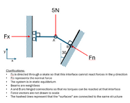

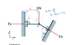
1738354974883.png
 
Replies continue below

Recommended for you

One quick clarification: Fx is a resulting force, not an input. You do not need to solve for Fx. I drew the vector just to help visualize the reaction force at that surface. Sorry for any confusion.
 
I agree that it is 10kN. That is, assuming that isn't a hinge where the load is applied. 5kN/sin(30°) = 10kN
 
I'll bite... Fn=10N?
Yes, assuming we are ignoring non-linear effects (and obviously there isn't enough information to evaluate those), it's hard to see how there could be any dispute that the resultant force has to be 5/sin(30) = 10.
 
Sum moments about Point A and show that there isn't any tangential force at B, then sum vertical forces to find the 10kN as above.
It seems to me there would be more potential error in going from the actual item to this simplification than in solving the system shown.
It is unstable at the left end, so it requires a weightless skate. If a fly lands on the skate, the system collapses.
 
I'm curious what the trick here is (considering you're getting PHDs involved), but I'll take a shot:
  • Joint A must be in equilibrium, so at Joint A, the sum of forces in the y direction must be zero.
  • If Fny is the vertical component of Fn, then Fny = 5N.
  • Due to the geometry, sin30 = Fny / Fn, and thus, Fn = 2 * Fny = 2 * 5N = 10N.
 
Ha had it wrong, first pass ignored the existence of Fx, reworked and in camp Fn=10n

1738362526660.png
 
Last edited:
if A and B are pinned, isn't this unstable? pt A just snaps thru as the left side slides up.
Middle must be rigid connection or a cranked member, otherwise yea it would just fail in the middle and you'd be unstable. But A and B being pins doesn't inherently make it unstable.
 
if A and B are pinned, isn't this unstable? pt A just snaps thru as the left side slides up.
Yes, I should have read the notes, I assumed continuity at point A. If it is pinned at A, it is in static equilibrium in the same way that a free-standing column that is pinned at the base is in equilibrium under a pure axial load; i.e. it is highly unstable.
 

Part and Inventory Search

Sponsor