Eng-Tips is the largest engineering community on the Internet

Intelligent Work Forums for Engineering Professionals

  • Congratulations waross on being selected by the Tek-Tips community for having the most helpful posts in the forums last week. Way to Go!

Calculating Lifting Plate, Pad eye stresses

Status
Not open for further replies.

Hanson Gill_1983

Mechanical
Aug 16, 2017
21
0
0
IN
Dear All,

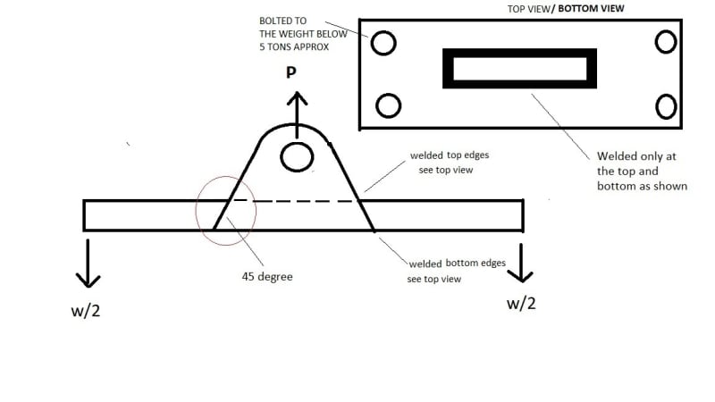
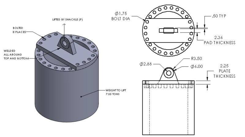
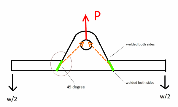
iam designing a lifting plate see attached picture. The pad eye is interfaced with plate at 45 degree and welded as shown.

I can calculate the double plane shear, bearing stress of the pad eye and the bending stress of the plate. But im not sure how to calculate the stresses acting at the welded joints, and the shear, bearing stress for the 45 deg angled profile.


Please any lead would be much appreciated. Thanks.

Regards,
HANSON
 
 https://files.engineering.com/getfile.aspx?folder=5bf63c48-aecb-4ae4-ac06-ec99328166f5&file=Lifting_plate.jpg
Replies continue below

Recommended for you

Hanson - I'm not sure that I'm interpreting the sketch correctly... anyway here is my take on the problem:

Lifting force (P) is applied at the top of the lifting eye hole (force shown in red).

Force passes only through the welds (shown in green). To simplify the solution, assume all forces pass through the centroid of each weld line.

Force from each of the two welds (shown in orange) meet at the top of lifting eye hole. These two forces are equal and the vertical component of each is P / 2. Note that angle of these forces, measured from horizontal, is NOT necessarily 45[sup]o[/sup], but the angle can be calculated using trigonometry.

Lifting_plate-600_bcuqfi.png


[idea]
 
I am not sure how thick the plate is or what your loads are but this looks like a bad idea to me. Just use one plate and slope it out to the sides.

An important consideration is fatigue. If this is a lifting device intended for frequent use you need to follow "Design of Below-the-Hook Lifting Devices" referenced earlier and carefully look at fatigue requirements, especially in the welds if you go that route.
 
Moment is going into that weld from the cantilevered ends. I agree with @Ideem: looks like a bad idea and I'd weld the lug to the top of the plate.

In the meantime, track down the Ricker paper for lifting lugs and the ASME Below-the-Hook manual.
 
Gents,

Thank you very much for the information and references.

Sorry, i haven't mentioned the weld profile correctly. Please find the actual weld profile image attached for reference.
The pad eye is welded at the top and bottom edges along the horizontal axis only.

Thanks,
Hanson

Lifting_plate_design_dwnc6u.jpg
 
Hanson Gill_1983:
That is not a particularly well conceived design for a lifting device under most normal conditions. Engineers are supposed to solve problems, and yet they do such a poor job of defining their basic problem that even another engineer has to play 20 questions to guess at what they are really trying to do. You would be surprised at how much real info. a well proportioned sketch with some meaningful dimensions, loads, a couple different views, real meaningful engineering info., will provided an experienced engineer in assessing your problem. As you are doing your sketch ask yourself, ‘what info. do I need to design and solve this problem?’ Then, show that on the drawing. How long is the bottom pl., along with its width and approx. thickness? What are the hole sizes, bolt sizes and c. to c. hole dimensions? Realize that the vert. lifting pl. and its pin hole must be designed for the total load P, which based on what you’ve shown is 20 tons, (4)(5tons). And, that the pin hole and the vert. pl. thickness should be matched to an adequately sized pin or shackle, maybe with a couple doubler pls. to make up thickness at the pin hole. Then, you are going to machine/cut a rectangular hole in the bottom pl. so the vert. pl. can fit up into that hole and be welded all around, top and bot.? Why not make the vert. pl. the full length of the bot. pl., but with sloped top edges, if you wish. Then, add a couple end pls. 8” high (some height) and the width of the bot. pl. and welded to the vert. and bot. pls. This protects the welds at the end of the vert. pl., and now you only have pl. bending from the vert. pl. out to the bolts to worry about, in terms of pl. bending and deflection. All-n-all, a much stiffer and cleaner lifting device.
 
I agree with other comments above. I would also investigate the effects of prying action as discussed in the AISC 14th edition on pgs. 9-10 through 9-13. Basically, as the plate starts to bend, the tensile forces in the bolts connecting the plate to the lifted object will increase above that due to the applied tensile force alone.

EIT
 
Thanks all..

The aim to lift a 7.55 ton load using the lift plate (with pad eye) as shown in the pic below.
Following are the stresses that i am able to calculate,
1) double plane shear due to shackle pin at pad eye hole
2) bearing stress for the pad eye hole / pin interface
3) 8 X bolt stresses due to hanging weight
_____________________________________________
4) Would like to know, how to calculate the plate bending stress by considering the plate as supported at both ends and loaded midpoint?
5) the pad eye being inserted into the plate from bottom through the slot and welded all around top and bottom. How to calculate the weld stress?

Any suggestions, improvements or book references are much appreciated.

Thanks.

LIFTING_PLATE_ASSEMBLY_igljkh.jpg
 
Why are you inserting the shackle into the plate? Weld it to the top

The bending stresses should be pretty straightforward. Max moment of PL/4 at the center for a simply supported beam?

There is an axial load at the center of your weld group. The weld stress can be found by simply using P/A. Really don't get why you're inserting the shackle, but I haven't taken the time to read through all of the comments.

Check the bolts for tension from the weight as well as prying. I assume you are using drill and tapped holes? Hopefully you aren't tapping both holes and trying to match the threads.

This is a textbook FEA problem if you have software. Don't use it without knowing the physical behavior of your design though...
 
Status
Not open for further replies.
Back
Top