Eng-Tips is the largest engineering community on the Internet

Intelligent Work Forums for Engineering Professionals

Calculating reaction forces

Status
Not open for further replies.

VFreshEngineer

Mechanical
Jan 7, 2022
14
0
0
NO
Hi,

I need to find the optimal placement for antivibration mounts. In order to do that, the reaction forces have to be calculated first.

Here is a FBD of the structure:
FBD_BaseFrame_nb9mrz.png


What will be the resulting reaction forces at support A?
 
Replies continue below

Recommended for you

Each load will produce a reaction on the three supports. This can be found numerous ways, but a moment distribution is probably the most direct way in spreadsheet program. Once you have the reactions for each load, you can superimpose them according to how they occur in time, relative to each other, i.e. sum the reactions from the loads that will occur at the same time. If some loads do not necessarily occur simultaneously, you'll have to look at whether those loads add to the reaction or subtract from it (Hint: F3 will produce a negative reaction at A).

Rod Smith, P.E., The artist formerly known as HotRod10
 
Hi VFreshEngineer

I would use the superposition method on this beam problem and remove the centre support. With the centre support removed, it then becomes a statically determinate beam and you calculate the reactions at the two supports but also the slope and deflection of the beam at the position of the middle support. Now at the middle support the slope and deflection should be zero, so now you revisit the beam section putting an unknown force upwards where the middle support would and recalculate the equilibrium so that you have zero deflection at the third support position.
See link below


“Do not worry about your problems with mathematics, I assure you mine are far greater.” Albert Einstein
 
Hello again,

GregLocock said:
Your table says 4 loads, your diagram says 3.
I see now how this can be confusing. The last load (nr. 4) is due to the weight of the beam itself, so the last force should actually be drawnn as an equally distributed load.

This is a 3D-problem, which I similified to 2D. Perhaps oversimplified? The frame it's not exactly made out of beams. It's made out of bended steel S355.
BaseFrame_edafhn.png


All of the loads will be present at at times, as they are representing the weight of the components that are mounted to the frame. Does it mean that I can sum all of the reactions to just have one force acting on the structure?
 

Hi again

It might be better to do this with a FE program package because that frame will have varying stiffness along its length due to its construction and I have no idea how accurate you need to be in terms of positioning the vibration mounts. That said you could calculate the reactions for one side of the frame using the superposition method, assuming the beam is a channel section which I assume from your last post but how accurate it would be is anyone’s guess.

“Do not worry about your problems with mathematics, I assure you mine are far greater.” Albert Einstein
 
slope and deflection should be zero

Slope at centre support doesn't have to be zero. Only the deflection to give you sufficient equilibrium/compatibility equation to solve for the 3 unknown vertical reactions.

In a statically determinate system, just having sum of moment about a few locations equaling zero, and sum of the vertical reactions and loads equaling zero is enough. But in a statically indeterminate system you need further equations to be able to solve. Usually this involves looking at deflection compatibility as others have noted. Taking away the centre support and determining what reaction gets you to zero deflection, as easy as that.

You should be able to solve one side channel for 1/2 the total load as per your original post. Apply the loads where they are applied in reality, don't sum them all to one load.

 
VFreshEngineer,

I read your post on Friday and I have given it some thought. I have worked on stuff similar to this.

Caveat: I make a distinction between shock mounts, and anti-vibration mounts, and I watch my terminology. In design in general, fifty to ninety percent of solving your problem is understanding what the problem is.

Your structure can be solved by double integration method if you assume it is flexible, and that it is sitting on an infinitely rigid base. This allows you to define boundary conditions that let you solve the statically interminate reactions.

In vibration analysis, your structure is infinitely rigid, and it is sitting on flexible mounts. Your optimal arrangement is for your mounts to be arranged symmetrically about your centre of mass. If your structure is set up symmetrically, each mount sees the same displacement and the same force. If your structure displaces a distance x up or down, each mount will continue to exert equal forces. These will a function of x, and your mounts' spring rate. If your structure rotates about the middle mounts, the fore and aft mounts will deflect in opposite directions, and the forces will vary correspondingly. Vibration is a dynamic condition. All kinds of weird things happen.

If your structure is not orders of magnitude more rigid than your anti-vibration mounts, then you have a weird and complex system.

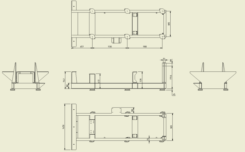
I have analysed a structure that sat on three sets of anti-vibration mounts. It was mounted inside an aircraft, so I had two problems.
[ol 1]
[li]The six mounts must be optimised for the mass of the device.[/li]
[li]The device must remain attached to the airframe in the event of an otherwise survivable crash.[/li]
[/ol]

Optimising was easy. All I had to do was look in the catalogue for mounts rated for one sixth the mass.

In a crash, the cup[ ]style mounts should fail when they reach the end of their travel, and the top of the cup shears from the vertical load. In a forward crash, this will happen to the two rear mounts. The middle mounts will still exert spring load. The load ratings for aircraft style mounts like these account for crash safety, but I assume that they are assuming you are using four mounts. In the potentially deadly crash, the rear mounts will tear out before the middle mounts see their maximum load. Then, the middle mounts would max out and see the impact load. I don't really understand how this failure works. I am not sure I can just assume that the middle mounts are that much more strain energy to be dissipated. I was not the designer, so I could not change the mount arrangement. I think I bumped the mounts up a load rating, making the vibration setup less than optimal. I was not a happy camper.

If you have crash safety issues, I recommend four anti-vibration mounts, appropriately sized.

--
JHG
 
Status
Not open for further replies.
Back
Top