Muaath123
Mechanical
- Apr 25, 2016
- 5
Hello guys,
I want to calculate the safety factor on container support design of gear box and I need your tips
The actual mass = 1600 kg
I assumed the mass to be = 2500 kg
= 2500 X 9.8 = 24500 N
The material is Steel A36 (Structure Steel)
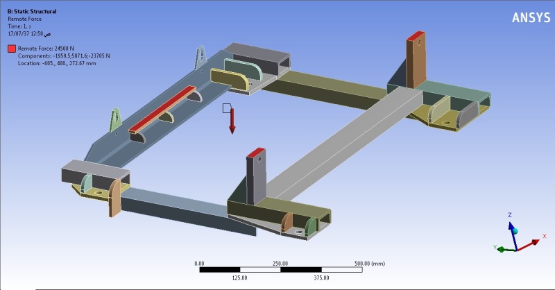
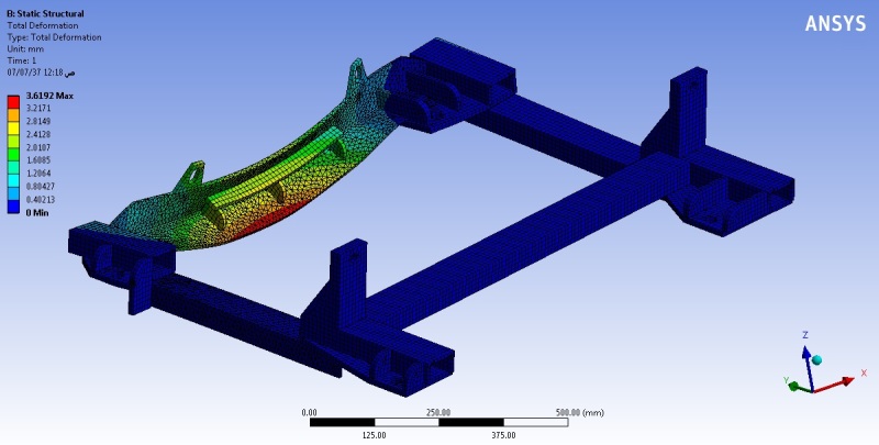
So, I choose static structure, performed the mesh and remote force (24500 N) to be applied in the center.
and the result is:
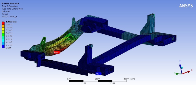
Total Deformation
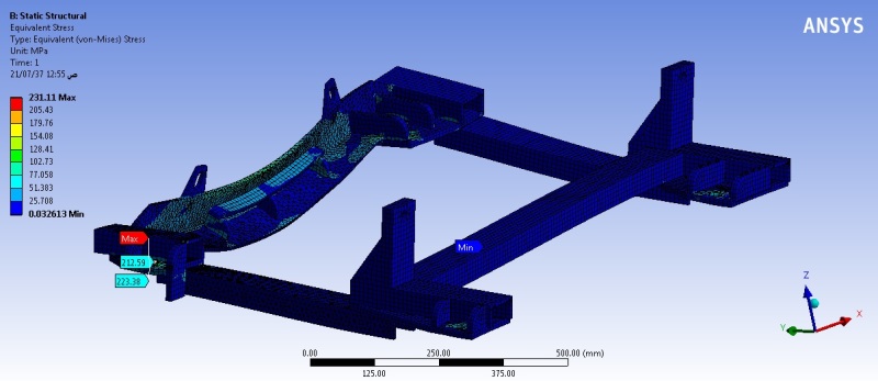
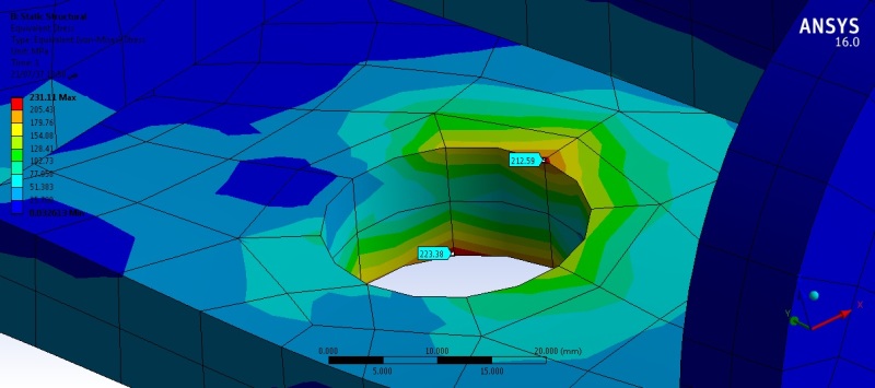
Equivalent Stress
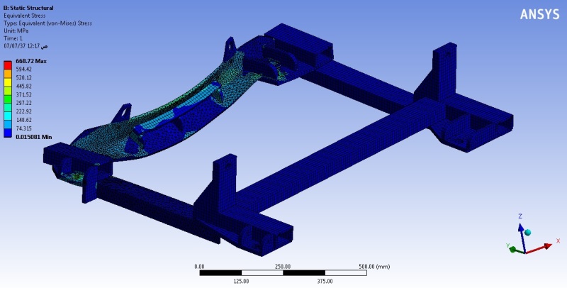
and the F.O.S equation will be:
F.O.S = max. strength / Design load
= 2500 (kg) / 668.73 (MPa)
= 3.73 > 1
I'm hope my calculation is right
Please if you have any tips or comment, share it with us
Thank you so much for your time
I want to calculate the safety factor on container support design of gear box and I need your tips
The actual mass = 1600 kg
I assumed the mass to be = 2500 kg
= 2500 X 9.8 = 24500 N
The material is Steel A36 (Structure Steel)
So, I choose static structure, performed the mesh and remote force (24500 N) to be applied in the center.
and the result is:
Total Deformation
Equivalent Stress
and the F.O.S equation will be:
F.O.S = max. strength / Design load
= 2500 (kg) / 668.73 (MPa)
= 3.73 > 1
I'm hope my calculation is right
Please if you have any tips or comment, share it with us
Thank you so much for your time
")

![[ponder]](/data/assets/smilies/ponder.gif "[ponder] [ponder]")
![[dazed]](/data/assets/smilies/dazed.gif "[dazed] [dazed]")